How to Test for Faults in Load Cells

Load cells may, from time to time, encounter faults that disrupt their performance. This article highlights common strain gauge load cell faults and how to troubleshoot them.
Common Load Cell Faults
The following faults are common to a typical strain gauge load cell:
- A sudden change in the zero balance value of the load cell,
- Unstable readings and random changes in the zero balance point of the load cell,
- Incorrect or overload readings for a known weight
- No reading at all
- Erratic output display upon applying or removing a load.
A different test exists to troubleshoot each of these situations; these tests are described in later sections.
Troubleshooting Load Cells: The Steps
Follow the steps in each subsection should you encounter any of the faults above.
1) Perform Preliminary Visual Checks
When these or other faults occur, it is important to verify the integrity of the weighing system before troubleshooting the load cell. This includes the following steps:
- Check the mechanical supports, load cell orientation and mounting surfaces for cleanliness, levelness and alignment. Use a straightedge or level if need be. (See Load Cell Mounting and Installation Best Practices.)
- Check load cell for dents, cracks, corrosion, excessive wear in the loading area, bending or buckling. Again a straightedge against the load cell may help discover any unwanted deformation. (See Quality Control: Load Cell Handling, Preservation and Storage Do’s and Don’ts.)
- Check the interconnecting cables at the summing box. All cabling should be free of cuts, crimps, exposed wire, etc.
- Check the connection of the summing box to the digital indicator panel.
- Check the excitation voltage source connections. Ensure the excitation voltage source provides a stable signal.
If visual checks reveal issues, correct these and determine if faults persist. If they do, proceed with troubleshooting the load cell.
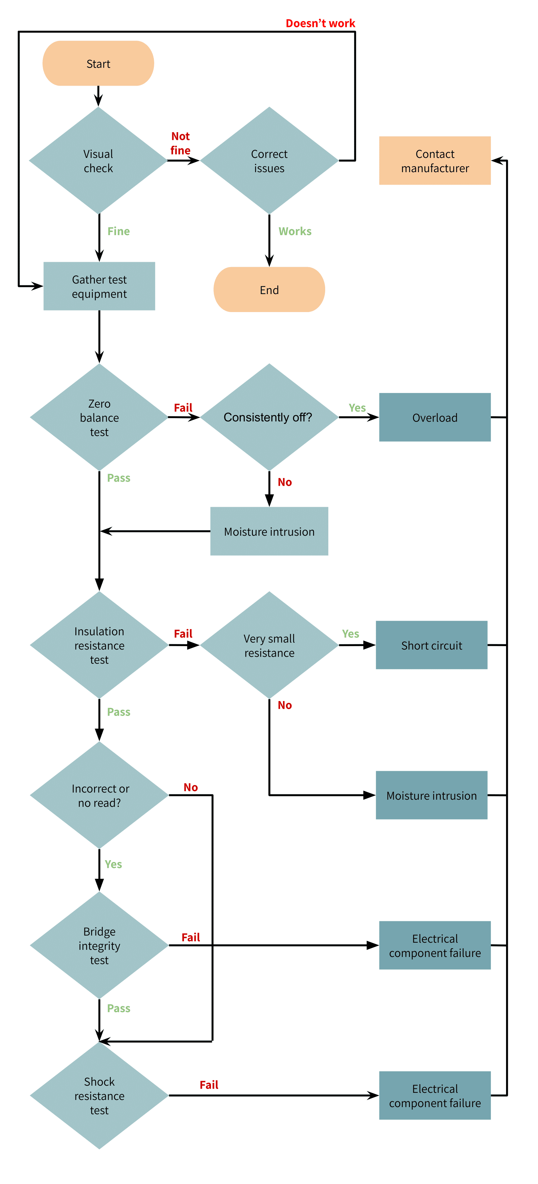
2) Gather Required Test Equipment
The remainder of the troubleshooting steps require the following test equipment:
- A high quality digital voltmeter and ohmmeter capable of reading from 0 – 50 mV and 4 – 20 mA with accuracy of ±0.1 mV and ±0.5 mA,
- A screw driver set,
- A mega-ohmmeter capable of reading 5000 ohms (or the insulation resistance given on the load cell data sheet, whichever is greater) with accuracy of 500 ohms at 50 V. It should be noted that the chosen mega-ohmmeter should not supply more than 50 V to the load cell, since voltages exceeding this can cause permanent damage to the load cell.
Upon obtaining the above, proceed with the following steps in order, as needed based on the trouble encountered. Alternatively, ANYLOAD offers a testing device that performs all of the required test functions.
3) Determine the Zero Balance
The zero balance is the output reading of a load cell at no load. For a multi-load cell measurement system, each load cell should be checked individually.
- Connect the load cell input terminals to a stable, low noise excitation/input voltage.
- Measure the voltage across the load cell output terminals with a millivolt meter (mV) and divide the result by the excitation voltage to obtain the zero balance in mV/V.
- Compare this value for the zero balance with the value in the product’s data sheet.
Expected result: Zero balance falls within values on product data sheet.
Test failure: Consistent zero balance changes may indicate the load cell has suffered permanent deformation due to overload or shocks. Drifts in zero balance over time may indicate moisture intrusion, which alters strain gauge resistance. In the latter case, very often the load cell will also fail at least one of the next two tests.
If the zero balance is not the problem or if test results seem to indicate moisture intrusion, perform the next test.
4) Perform an Insulation Resistance Test
An insulation resistance test is carried out when there are unstable readings and/or random changes in the zero balance point of the load cell. It measures the resistance between the load cell body and all its connected wires, as follows:
- First, disconnect the load cell from the summing box and indicator panel.
- Connect all the input, output and sense (if equipped) wires together.
- Measure the insulator resistance between the connected wires and the load cell body with a mega-ohmmeter.
- Then measure the insulation resistance between the connected wires and the cable shield.
- Lastly, measure the insulation resistance between the load cell body and the cable shield.
Expected Result: The insulation resistance should match the value in the product’s load cell data sheet.
Test Failure: A lower value shows an electrical leakage caused by moisture or contamination; a very low value indicates a short circuit, giving unstable load cell outputs.
If the insulation resistance is not the problem, proceed to the next tests.
5) Perform a Bridge Integrity Test
A bridge integrity test is done when the weighing scale indicates overload, gives incorrect readings for a known weight, or does not give any reading at all. It involves measuring the output resistance, input resistance and the bridge balance, through the following steps:
- Disconnect the load cell from the junction box or measuring devices.
- Measure the input and output resistance across input and output terminals of the load cell with an ohmmeter.
- Compare the resistance values with those in the product data sheet.
- Compare the resistance from the negative output lead to the negative input lead with the resistance from the negative output lead to the positive input to obtain the bridge balance.
Expected result: The difference between the two test readings of the bridge balance test should be less than or equal to 1%. The input and output resistances should be less than 3 kilo-ohms.
Test failure: Differences in the bridge balance measured values exceed 1% or the input and output resistances exceed 3 kilo-ohms. This happens due to electrical component failures or an internal short circuit. The cause of these problems is generally lightning strikes (overvoltage), excess temperature or physical damage from improper handling.
Note: Never use a mega-ohmmeter to measure the input and output resistance of the load cell, as it operates at a voltage level (50V) far greater than the load cell’s normal input and output voltage and can therefore damage the load cell.
6) Perform a Shock Resistance Test
A shock resistance test is carried out if the load cell gives erratic output display when load is applied or after load is removed. The steps are:
- Connect the load cell to a stable voltage source.
- Connect a voltmeter to the output terminals.
- Gently tap on the load cell with a small mallet to mildly shock it. Note: For very low capacity load cells, take care to not overload the load cell while performing this step.
Expected Result: When checked, the readings should not become erratic; they should be stable and return to the zero point.
Test Failure: If the display shows erratic readings, then there could be a failed electrical connection within the load cell; otherwise, the culprit is likely a compromised glue layer or bond between the strain gauge sensor and load cell body.
Conclusion
If the load cell proves to be defective after all the above tests for faults are performed, it can be returned to the OEM for repairs or replacement. Tacuna Systems supports all of its products and is available to help troubleshoot and resolve any product issues.