How to Measure Axial Thrust Using a Load Cell

Measuring an axial thrust load with a load cell requires a clear understanding of both axial thrust and load cell designs. This depth of understanding clearly influences the choice of measuring technique and the load cell type to use. Therefore this article aims to provide a foundation for this knowledge. It explains axial thrust in rotating equipment, using the specific example of a centrifugal pump.
Axial Thrust Definition
By examining the meaning of each word “axial” and “thrust” individually, its compound meaning becomes apparent.
“Axial” is an adjective that describes something relating to the axis of an object. In this case, the axis of an object is an imaginary line usually parallel to the vector of force (such as gravity) applied on the object when it is resting in a stable position. If the object is irregular in shape, it is generally symmetrical at any cross section that is perpendicular to the axis.
Thrust is a noun that describes the action of pushing/propelling an object against a platform in a specified direction. It is the vector of force in the above definition.
Putting the two meanings together, axial thrust refers to a propelling force applied along the axis (also called axial direction) of an object in order to push the object against a platform in a particular direction. The direction can be negative (tensile) away from the platform, or positive (compressive) toward the platform depending on the point of reference.
Axial thrust can also refer to the driving force generated in propulsion of an airplane, a pogo stick, steam turbines, stage pumps, or double suction impellers.
For a closer look at axial thrust, the next sections will examine the specific example of a centrifugal pump. We choose this example since it requires a load cell to balance axial thrust.
Axial Thrust Example: Centrifugal Pump
A centrifugal pump is a machine that converts rotational kinetic energy (of a rotor) to hydrodynamic energy for the purpose of transporting fluids from one place to another. It generates centrifugal forces to push out the fluids entering it.
The term suction side refers to the inlet side of the machine through which fluid particles enter. The term discharge side refers to the outlet side through which the fluid particles escape. The pressure at the discharge side is greater than the pressure at the suction side.
Components
Centrifugal pumps have two major components other than the driving unit (e.g. an electric motor).
These are:
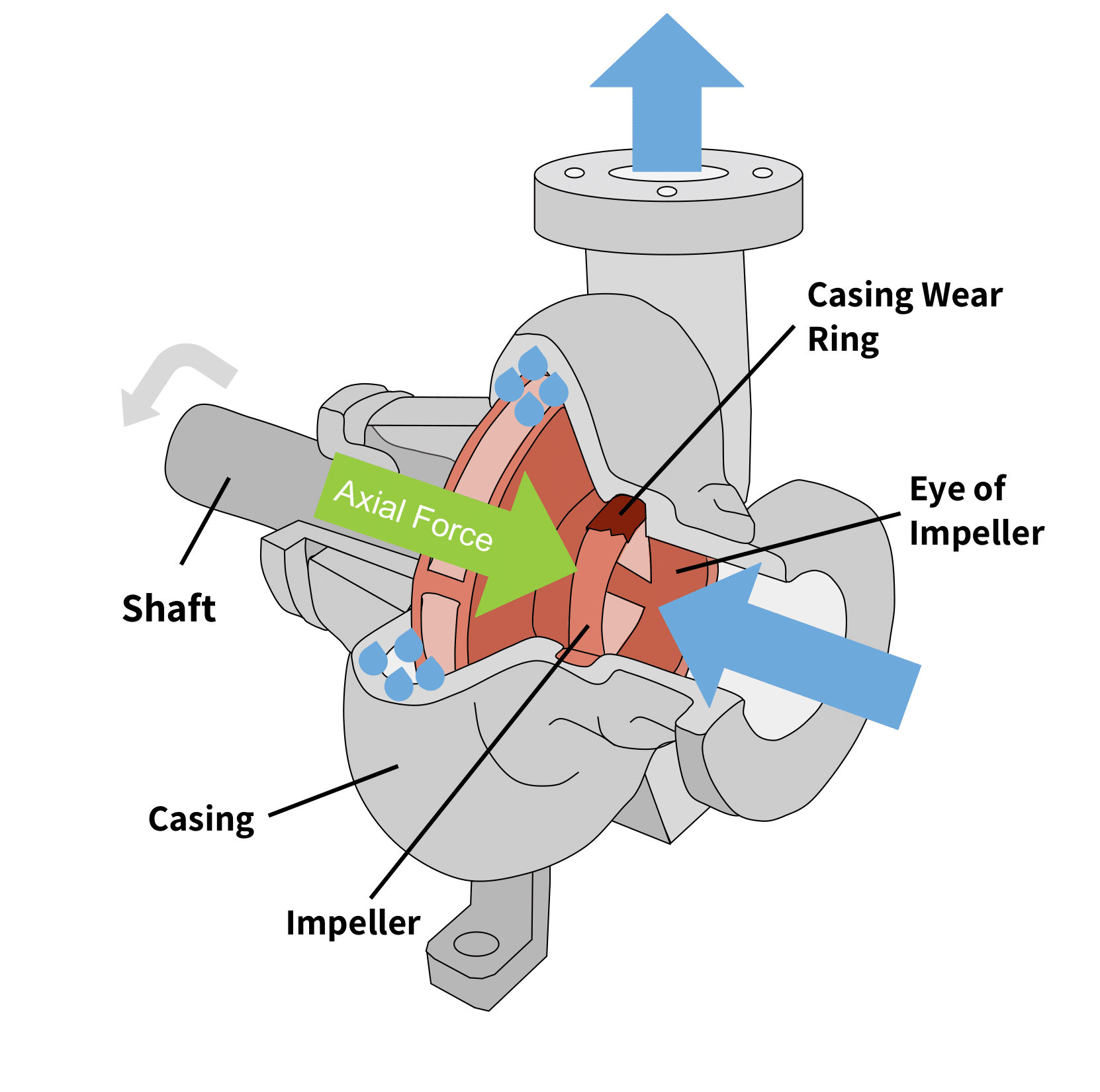
- The impeller: This component has backward curved vanes or blades. The impeller is a rotating part of the centrifugal pump that connects to the driving unit with a shaft. The rotating impeller vanes push the fluid particles towards the outlet. There are different types of impellers: the open impeller, semi-open impeller and shrouded impeller.
- The volute casing: This is a specially-designed spiral casing whose cross-sectional area increases along the direction of fluid flow. This design helps to force fluid out the discharge side.
The casing protects the pump and houses balancing holes. The balancing holes are points where balancing weights are affixed; these weights ensure that the pump’s internal components’ collective center of mass aligns with the center of mass of the driving unit’s rotor (motor’s rotor shaft).
The other parts of the centrifugal pumps are:
- The shaft that connects the impeller to the driving unit.
- The bearings located on the shaft that help maintain radial and axial thrust load clearance. A double suction impeller has bearings on both sides (front and back).
- The sealing which prevents dirt and fluids from entering the parts of the pump.
How Axial Thrust Builds in Centrifugal Pumps
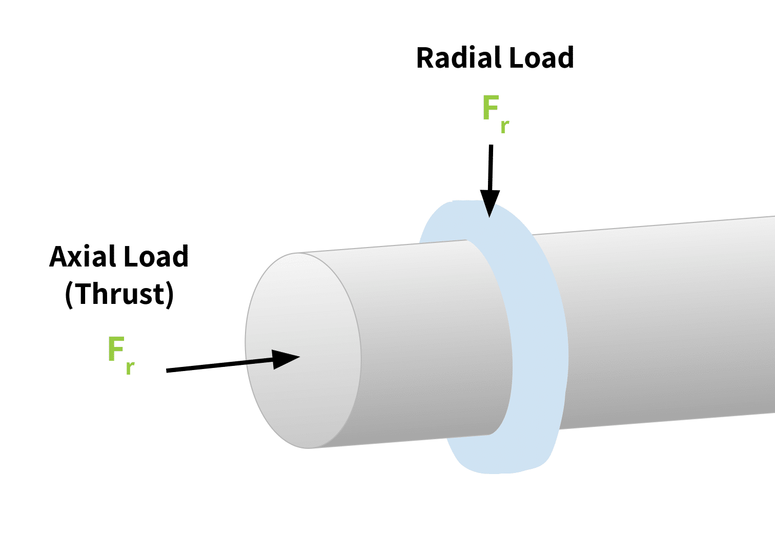
In single stage pumps, as the device powers on and the shaft begins to rotate, two sets of forces act on the shaft (refer to Figure 1). The first are radial forces created by unbalanced pressure due to the casing design (recall it widens along the fluid path). The second are the axial forces, caused in part by the pressure difference between the shaft where it directly attaches to the back side of the impeller and the front side of the impeller.
As the fluid moves to the discharge side of the pump, parts of the liquid tend to push against the casing thereby pushing the shaft outwards along its axis through the driving unit. This force acting along the shaft’s axis also contributes to the axial thrust.
Other axial forces on the shaft occur with use. Over time, fluids carry dirt particles that deposit on the blades, causing an unbalance in the system. This generates axial thrust components on the shaft and the motor.
In multistage pumps axial thrust on the shaft is more common. The difference in pressure between multiple impellers further contributes to a misalignment in the total axial balance.
Balancing Axial Thrust
The process of balancing axial thrust is very important to the pump’s proper functioning. A force offsetting the axial thrust accomplishes this.
Some offset techniques include:
- The use of thrust bearings to support high axial loads especially in heavy-duty centrifugal pumps.
- The use of a balance piston. An opening beneath this balance piston ensures the fluid flows back towards the pump inlet. Without this opening, axial thrust on the shaft will increase from the fluid flow exerting pressure on the piston.
- Proper alignment and arrangement of the impellers.
This balancing reduces stress and damage to the pump structure. Specifically it reduces stress exerted on shaft bearings (wearing rings, loose rings, and thrust bearings) and prevents damage to the pump’s protective seal.
The Role of Load Cells in Balancing Axial Thrust
As highlighted in the example, balancing axial loads is important for the proper maintenance of the equipment bearing these forces. But how does one know the extent of the axial load, particularly since it builds over time and use? This is where load cells, such as those in the Tacuna Systems product line, are important.
Load cells are sensor devices. Sensors are used to detect a physical stimulus and then produce an output (electrical or mechanical) that is proportional to that stimulus. Load cells detect loads and forces, such as axial thrust.
Several types of load cells (described in An Overview of Load Cells) exist. However for many applications, including for measuring thrust, a strain gauge load cell is the most convenient and cost-effective. It is a passive transducer, meaning it requires an excitation voltage. Figure 3 below shows a simple strain gauge load cell.
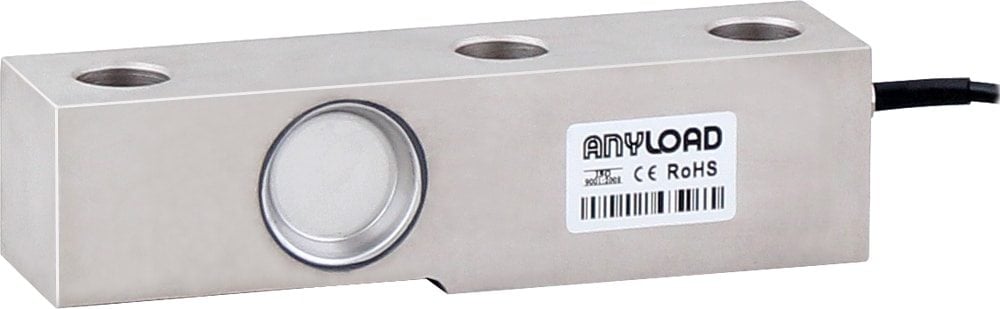
When a force is applied to the loading point of this type of load cell, the strain gauges within it deflect. This increases the overall electrical resistance across the gauges. This measured difference in resistance creates an electrical signal directly proportional to the force applied by the load. This signal is generally very small, on the order of millivolts, and must be amplified for proper readings. (See The Versatile Strain Gauge Load Cell for a more detailed explanation of this device’s operation.)
This load cell output is processed and signaled to displays that notify operators if the axial thrust balancing mechanisms are working. They can also be the input signal of control systems that stop the rotating machinery before damage can occur, should the balancing fail.
Designing a Simple Axial Thrust Measuring System
The sections above establish how axial loads are produced and that they must be mitigated. This section brings these two ideas together by explaining how to quantify axial thrust.
The steps to create an axial force measurement system follow.
1) Determine The Maximum Force
It is essential to determine the limits of the force that the propeller or the engine will generate. This is done mathematically using the constants and variables of the engine. This step is necessary in selecting a load cell with a rated output capacity equal to or greater than the expected maximum force.
2) Determine The Direction Of The Force
Thrust is a reaction force that acts in the opposite direction of the original force generated in an engine. Therefore both compression and tensile forces act on the spinning shaft. The selected load cell must support both directions of forces.
3) Select The Load Cell
Each load cell manufacturer produces a datasheet giving maximum rated loads and other figures pertinent to its operating environment. (See How to Read a Load Cell Datasheet.) Select the load cell that suits the basic requirements determined in steps 1 and 2, meets the requirements of the operating environment, and has the required certifications. Certifications ensure the load cell device has been tested and approved for safe use.
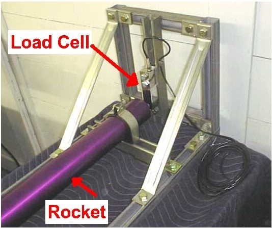
4) Construct a Thrust Stand/Frame
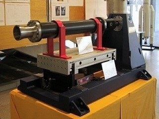
The load cell will always require a mounting kit to ensure an accurate result. This mounting kit is then built into a thrust frame (see Figures 4 and 5), which must adhere to the following:
- It must be a fixed support frame with the mount on one end for the load cell.
- It must have an alignment system to ensure the thrust axis of the engine is parallel to the direction of load cell’s force measurement trajectory, at the application point. This will prevent issues of off-axis loading. A simple alignment system might incorporate optical devices like lasers. For centrifugal pumps, alignments might be off at times due to unbalancing; this requires self-adjusting alignment systems in the frame/mount design.
5) Condition the Output Signal
A strain gauge’s output, unconditioned, is usually very small (of the order of mV) and can be affected by noise. Conditioning filters this background noise, amplifies the filtered signal and converts it from an analog to digital signal. A microcontroller can further process the digital signal to display the thrust force and desired units of measurement. (See Why do I need a Load Cell Amplifier (and Other Signal Conditioners)?)
6) Calibrate the System
Calibration ensures the force measurement system gives accurate results, both at installation and periodically over continued use. A simple calibration system for this purpose might use a screw jack driven by an electric motor to apply both compressive and tensile forces to the load cell through a series of levers and pull rods. Further calibration procedures give the tare of the load cell and also set up automatic calibration over use. Our Tacuna Systems cell calibration system is an example.
7) Mount and Test
The final step is to mount the engine in the measuring system. Perform all the necessary checks before powering on the system. Ensure this done in a controlled environment under proper supervision and approval.
Conclusion
This article has explained the idea of axial forces and their impact on the longevity of a rotary system such as a centrifugal pump. It has also explained the use of load cells to quantify these forces so that they can be mitigated. Tacuna Systems provides a variety of load cells for this application.
References
- An Overview of Load Cells
- The Versatile Strain Gauge Load Cell
- Centrifugal Pumps by Dan Campbell, Noah Brown, John Cox
- Centrifugal Pumps by Christian Allerstorfer