The following paper was provided by Southern Illinois University Edwardsville as an example of the use of load cells in practical research applications.
Dr. Paul E. Brunkow, PhD
Department of Biological Sciences
Southern Illinois University Edwardsville
We are interested in studying the hydrodynamic characteristics of freshwater snails in my lab in the Department of Biological Sciences at Southern Illinois University Edwardsville.
While some studies have been performed on marine intertidal snails, which tend to be much larger and live in extreme water velocities, to our knowledge no work has been done using freshwater snails, which are much smaller and live in streams and rivers. We are particularly interested in learning whether hydrodynamic demands have shaped the evolution of shell form in snails of the family Pleuroceridae, a very diverse group of species concentrated in the SE United States. Pleurocerid snails range from 5 mm to 20-30 mm in length and possess shells that may be spiny, ridged or relatively smooth, and either short and squat or long and slender.

Design challenges in this project have been complex, especially for non-engineering biologists. We are not using live snails, as live Pleurocerids can be extraordinarily stubborn and uncooperative; instead, we are scanning shells and printing accurate replicate models on a 3D printer. Scanning and printing shells allows us to duplicate shells in museum collections, thus eliminating the need to collect individuals of threatened or endangered species. Additionally, measurement of drag and lift must be made while the shell is in contact with the surface of a recirculating flume; thus, we need to eliminate friction between the shell and the flume, and we must be able to accommodate changes in lift (either positive or negative) with changes in water velocity. Drag and lift forces on these shells, at the range of water velocities tested (10 – 100 cm/s), will be very small (likely < 100 mN).

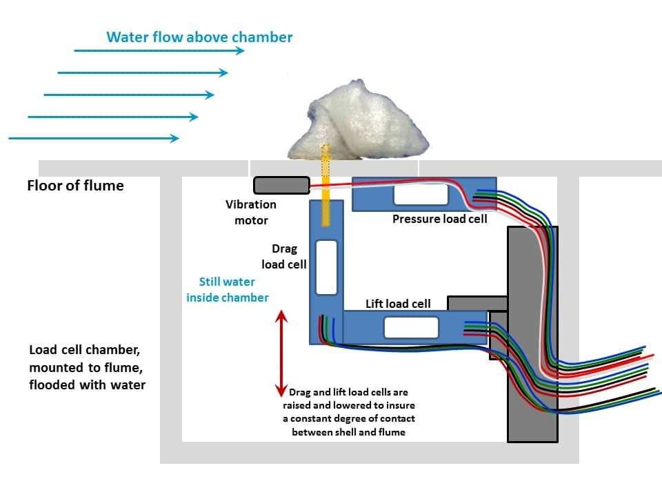
Our current sensor design utilizes load cells scavenged from old digital balances, pre-configured with strain gages in a full bridge circuit. Two load cells mounted at 90 degrees to each other measure drag and lift forces acting on a shell; there is no cross-talk between these load cells in the range of forces being measured. The shell model is mounted to the top of the drag load cell by way of a brass pin going through a hole in the flume floor. The drag and lift load cells are mounted to a Z-axis mechanism comprised of stainless steel and 3D printed parts which allows for raising and lowering the load cells with a high degree of precision. The third load cell measures the pressure with which the shell model is in contact with the flume.
When water flow is brought to a target velocity, the shell is raised and then lowered until it just touches the flume, as indicated by output from the pressure load cell. Difference in the change of output between the pressure load cell and the lift load cell is a measure of hydrodynamic lift acting on the shell. We then activate a small vibration motor (as would be found in a cell phone) that is epoxied to the pressure plate, to reduce friction between the shell and the pressure plate; drag induced by water flow over the shell can then be recorded by the drag load cell.
Output from all three load cells is amplified and conditioned through the EMBSGB200 strain gauge conditioner/amplifiers from Tacuna Systems; kudos to Chris Lange at Tacuna Systems for answering many questions and providing advice on the use of load cells and amplifiers in this project! Output is then digitized through a DATAQ DI-710 digitizer and visualized, recorded, and analyzed using DATAQ’s WINDAQ software. Preliminary observations and calibrations are promising that the sensor design is working as planned and we hope to be collecting accurate data soon.


