
Ordering from Tacuna Systems FAQ
Why should I select Tacuna Systems load cells and accessory products?
At Tacuna Systems, we strive to ensure the success of our customers’ projects through our responsiveness, personalized product support, and design services. To help these projects realize their goals, we offer a wide variety of distributed load cells and accessory product lines from industry-leading manufacturers (e.g., ANYLOAD, AmCells, REMO, Omega, Vishay, etc.), in addition to our own customizable Embedded Strain Gauge/Load Cell Amplifier (EMBSGB200 series), all manufactured to the highest quality.
Our Commitment: “Being a small business, we are able to offer our design expertise and services quickly and expertly. We take great pride in providing free consultation for product design and prototyping to all our valued customers.”
Do I need to order through a request for quote/phone order or can I just buy online if I know what I want?
Tacuna Systems wants our ordering process to be simple and easy for our customers. If you know exactly what product you are looking for, you can purchase it through our online cart. We also offer custom quotes and complementary consulting when you are not quite sure which product best meets your design needs.
What forms of payment do you take?
Tacuna Systems accepts American Express, Visa, MasterCard, Discover, PayPal, and Google Pay through our secure online payment system.
What is Tacuna Systems’ warranty?
We carry a one-year standard warranty against defects. You may return any unopened/unused purchase within 30 days. A 20% restocking fee may apply to items that require recalibration (opened electronics/load cells) if they are not defective and can return to inventory. Please contact us immediately with any potential warranty issues.
Do you offer any discounts?
Tacuna Systems offers several discounts: A student/educational institution discount, and loyalty discounts for over 5 lifetime purchases or for lifetime purchases totaling over $2000. We also offer a Price Match Guarantee.
What types of customization can you do for load cells?
Our lead supplier, Anyload, can modify or customize load cells to your specifications. Common modifications to standard load cells include:
- Cable length, type, or connector changes to match existing cabling, environmental requirements and dimensional constraints.
- Mounting hole thread size alterations
- Embedded surge protection
- Overload or sensitivity adjustments
- Material or coating changes, including non-magnetic materials.
Further customizations to existing load cells include:
- Building with unique dimensions to fit your weigh system structure
- Modifying output signals for various interfaces, including digital signaling interfaces
- Building in multi-bridge redundancy
- Designing for environmental extremes such as high- or low-temperature, radiation, underwater, or high-pressure washdown situations, and vacuums.
- Optimizing for In-Motion or Process Weighing
Finally, we can develop a fully customized load cell for your application to accommodate
- Extreme miniature dimensions,
- Legacy load cell replacement,
- Medical imaging constraints,
- Undersea environments,
- Space and low-gravity environments
I am working on a weighing system project and cannot find needed information. Can Tacuna Systems help?
Yes, Tacuna Systems engineers have extensive R&D and technical support experience to guide you through the process of concept, design, accreditation, and manufacturing of your project. We are proud to provide an array of complementary design services including:
- PCB layout,
- Schematic capture,
- Product design and conceptualization,
- Prototype runs and
- Project consultation.
Our products and services meet quality standards that give accurate, reliable, and certified results as quickly and easily as possible. Refer to Tacuna’s website page, Tacuna Systems Force Measurement Solutions for more information on the various ways we offer specific project recommendations.
Getting Started With Load Cells FAQ
What is load cell sensitivity?
The sensitivity of a load cell measures how its output signal changes as the load cell excitation voltage varies when subject to a load at rated capacity. Systems that have low sensitivity ranges or are of lower quality will not be able to detect small changes that occur when a load cell experiences a force from a minimal weight.
Typical unamplified analog load cells have a sensitivity rating in units of mV/V. This load cell sensitivity rating is specified on a load cell data sheet often in the 1 mV/V – 3 mV/V range. Most quality load cells will come with a factory load cell calibration sheet which specifies the actual sensitivity rating for that individual load cell. This load cell sensitivity value can be used to convert the load cell’s output to scientific units of weight or force. (See our FAQ below on this topic; also our article What is the Lowest Weight a Load Cell Can Measure provides additional guidance.)
What is the difference between Full Scale Output and Rated Output?
Quite often these two terms are used interchangeably. However, they can have different meanings. Rated output is the load cell’s electrical output when it is loaded to its rated capacity load. Full scale output is generally the range of output values (also called the span) throughout the measuring range of the load cell. That is, it is the output value at maximum load minus the output at minimum load.
It is also important to point out the subtle difference between the maximum load and rated capacity. Again, quite often they are the same. The rated capacity is the maximum load where the calibrated load cell still behaves per its data sheet specifications. If the given maximum load is less than this value, it is generally application-specific and considers other factors such as tare weights or other possible load components, to hedge against exceeding the rated capacity load.
Figure 6 in our Force Measurement Glossary illustrates these terms.
What is the difference between Rated Capacity Load, Maximum Load, and Safe Load Limit?
The rated capacity is the recommended maximum load for a particular load cell. All load cells have a range of loads where the output signal is proportional to the load; that is the load-induced strain gauge deformation produces an output signal having an approximately linear relationship to the strain. When the rated capacity is in this range, the strain gauge produces outputs within the errors printed on the accompanying load cell data sheet.
The maximum load is equal to or typically within 10% of rated capacity (per OIML guidelines). Its value is the maximum recommended load for a particular load cell application, accounting for any environmental or other factors that may require a margin between maximum load and rated capacity.
The safe load limit (or safe overload) is the highest load that will not cause the strain gauge to undergo permanent deformation. Higher loads will exceed the elastic limit of the strain gauge material. The safe load limit is usually 300% of the rated capacity. Knowing the safe load limit is important, particularly for outdoor applications, since forces other than the measured loads can act upon the load cells. For example, winds may exert forces on the measured loads, adding forces to the strain gauges that may exceed the safe load limit.
Figure 6 in our Force Measurement Glossary illustrates these terms.
You sell “Weigh Module and Mounts” in your store. Why should I purchase these?
The short answer is that they protect your investment by extending the life and improving the accuracy of your load cells. Therefore, Tacuna Systems highly recommends weigh modules for specialized applications.
Load cells can be installed with general mounting hardware. However the modules, or mounting structures we sell are adapted to load cell installations in specific applications such as silos, truck scales and hoppers. This provides distinct advantages including:
- Ease of installation/maintenance. Bolt holes are more accessible when using a module; some modules allow load cell replacement by removing only two bolts.
- Overload protection. Modules often incorporate mechanical stops to prevent catastrophic damage to the load cell should an accidental overload condition occur.
- Skew correction. If the ground and hopper are not planar, you will get inaccurate readings from the load cells. Some modules compensate for this condition, giving much more accurate readings.
- Lateral movement. Because everything in a measurement structure expands/contracts vs. temperature, load cells hard-mounted to that structure will be most accurate at temperatures close to those at installation. When the structure expands/contracts, the load cells must resist the expansion/contraction and considerable side loading can take place. This causes undue stress on the cell, which causes not only potential damage, but errors in load cell output (which can be significant!).
For a comparison of different load cell mounts, see A Comparison of Tacuna Systems Load Cell Mounts and Modules. Also see our article, Load Cell Mounting and Installation Best Practices.
Can I deploy a load cell in a measuring system without a load cell mount or module?
Absolutely. However this method only works well when the contact points of the load cell (installation bolts and load-bearing point) are the only surfaces that contact the surrounding structure and load (respectively). Also this system must ensure the load is aligned in the intended direction of the load cell at the appropriate load point at all times.
For high-performance applications or applications where external forces or environmental conditions have a significant effect, the system should incorporate load cell modules. Common examples are vessel weigh systems, such as silos and hoppers.
Which load cell material is best for my application: alloy steel, aluminum, stainless steel, or tool steel?
Many factors influence the decision to purchase a load cell, such as cost, weigh application (e.g., object size, object weight, placing the object), durability, environment, etc. Each material used in the construction of a load cell has benefits over the other for each factor. However, the primary factors influencing choice of material should be the application’s environment, and the responsiveness of the material to load stress (elastic modulus) vs. its elastic limit relative to the maximum load it will need to withstand.
For example, chemical processing facilities find that stainless steel load cells are more practical; aluminum is more durable and responsive to stress than stainless steel; aluminum is cheaper than alloy steel; stainless steel load cells endure heavier weights better than aluminum or alloy steel load cells; tool steel is best for dry conditions; alloy steel is more durable than aluminum and can endure higher weight capacities; stainless steel load cells are more expensive than tool steel or aluminum.
Some additional benefits of alloy steel, aluminum, stainless steel, and tool steel are as follows:
- Alloy Steel is the most common material for load cells. It is suitable for single and multiple load cell applications, and limits creep and hysteresis. The most popular alloy used is alloy 4330.
- Aluminum comprises low capacity, single point load cells, and is not ideal for moist or harsh environments. It is best for these low load applications over other materials since it responds most to stress. The most popular aluminum is alloy 2023 because of its low creep and hysteresis.
- Stainless Steel is a more expensive option, but it performs the best in harsh conditions. Stainless steel alloy 17-4 PH has the best overall performance for use in the spring element. It can withstand corrosive chemicals and excessive moisture while maintaining the appropriate hardness. However, some pH levels can corrode even stainless steel. (See the next question.)
- Tool Steel is a good load cell material particularly for large loads because of its hardness. Its cost-to-performance ratio is better than with other load cell materials. Tool steel is suitable for single and multiple load cell applications, and limits creep and hysteresis.
Contact Tacuna’s Load Measurement Consulting service for specific project recommendations.
Can stainless steel load cells still corrode?
Yes, stainless steel load cells absolutely can corrode. “Stainless steel” does not mean “corrosion-proof,” and this is a common and important misconception in load cell selection. When choosing a load cell, consider these guidelines:
- For dry corrosive environments (e.g., dry chemical powders), environmentally protected stainless steel load cells may offer sufficient corrosion protection.
- Wet/washdown/chemical environments (dairies, food processing, chemical plants), will require hermetically sealed (welded-seal) stainless steel cells, rated IP66/IP68.
- Protect the cable entry, as this is often the weak spot for corrosion, regardless of body material. Moisture can wick through the entry and intrude through the whole element.
- Provide drainage away from cells, regularly clean accumulated debris, and protect cables from corrosive materials. (See Quality Control: Load Cell Handling, Storage and Preservation Do’s and Don’ts)
- Standard stainless steel mounting hardware (usually 304 stainless) may not meet the application’s corrosion resistance requirements. Upgrade to 316 stainless in chloride or acid environments.
What type of load cell sealing technique is best for my application?
The three primary load cell sealing techniques are environmentally sealed, hermetically sealed, and welded sealed. These methods protect internal strain gauges from moisture, dust, and chemicals, ensuring measurement accuracy and preventing sensor failure in specific operating environments.
An environmentally sealed load cell uses rubber booting, glue-on cover plates, or potting compounds to protect the internal gauge cavity. While this technique provides moderate protection against dust and humidity, it does not protect against water immersion or high-pressure cleaning. This seal type is best suited for indoor, dry-process weighing applications.
A hermetically sealed load cell uses a laser-welded cover to encapsulate the gauge pocket and a welded barrier at the cable entry (header) to prevent moisture “wicking.” This is the most robust sealing method, specifically designed for stainless steel sensors in heavy wash-down, chemical, or corrosive environments. Although the initial cost is higher, a hermetically sealed load cell is the most cost-effective long-term solution for harsh industrial use.
A welded sealed load cell features a welded gauge area similar to hermetic seals, but has a standard cable entry point (usually with a strain relief) rather than a welded header. This design protects the internal electronics from occasional splashing or moisture but is not ideal for continuous submersion or heavy wash-down. A welded seal is a mid-tier protection level suitable for environments with only occasional equipment cleaning.
What does the IP65 (or similar) marking on a load cell mean?
The “IP” rating or “international protection” (also sometimes “ingress protection”) rating indicates how well the load cell resists intrusion by liquids or debris into its electronics. See the document What Does the IP Rating on a Load Cell Mean? to interpret specific numerical values within the rating. Or, click here to see an infographic that summarizes the rating scale. From the infographic, we can determine that a marking of IP65, specifically, means the device is dustproof and can withstand water intrusion when exposed to sprayed jets of water. The sealing methods in the previous question help determine this rating.
Load Cell Connectivity FAQ
What is excitation voltage?
Load cells require an excitation voltage to produce an output signal. This is directly related to the fundamental workings of the internal Wheatstone bridge. Manufacturers often list two load cell excitation values: “recommended” and “maximum”. As their names imply, the recommended value is the voltage the manufacturer suggests for best output results, and the maximum value is the voltage that should not be exceeded to avoid load cell damage. See “Does load cell excitation voltage matter?” below for further pointers on selecting excitation voltage. See The Versatile Strain Gauge Load Cell for more information on all aspects of this type of load cell, including excitation voltages and bridge configurations.
Does load cell excitation voltage matter?
As stated previously, load cells require an excitation voltage to produce an output signal. A higher excitation voltage will produce a higher output voltage swing from the load cell under a load. So, bigger is better, right?
Yes, to a degree. Larger signals are easier to measure and digitize. Additionally, assuming the noise is constant, the ratio of signal to noise (SNR) increases. This is good from a data quality standpoint.
However, a high excitation voltage has drawbacks. Higher voltages through the resistive strain gauges (which comprise the Wheatstone bridge) will cause more current to flow and heat the strain gauges. The cell body acts as a heat sink to keep the gauges cool. If the excitation voltage exceeds the rated maximum, excessive heating can result, causing signal perturbation or gauge failure. Additionally, in battery-operated devices, high excitation voltage (and thus, current) will cause the battery to deplete much faster than with lower excitation voltages through the circuit.
Excitation voltages lower than the manufacturer’s stated maximum are acceptable for the given load cell. The manufacturer’s recommended value is obviously best, but there is no harm in a lower excitation voltage. For example, 5V is a very common excitation voltage for modern load cells. Modern instrumentation amplifiers are much better than old designs and lower excitation voltages do not compromise their output signals. It is perfectly fine to use a 5V excitation amplifier with a 10V recommended excitation load cell. (However, the converse is not true!)
Finally, when choosing the excitation voltage, consider the common mode voltage produced by the cell’s output. The amplifier or other signal conditioning electronics must be able to handle this common mode voltage, whose value is half of the excitation voltage. For example, a 10V excitation produces a 5V common mode voltage. These amplifiers provide the excitation voltage to the cell so an external excitation voltage is not necessary.
Contact Tacuna’s Load Measurement Consulting service for specific project recommendations.
How does a load cell’s sensitivity relate to the display or interface I choose?
The output of the load cell per smallest unit of weight measurable must be greater than the input sensitivity of the display per digit of that unit.
For example, assume you have a scale whose internal load cell has a rated capacity of 50lbs, a rated output of 1mV/V, and a recommended excitation voltage of 10V. Assuming use of the recommended excitation, this means the load cell will output 10mV (1mV/V \(\times\) 10V) to the display when it bears a weight equal to rated capacity of 50lbs.
If the load cell can measure a weight as small as a tenth of an ounce (0.00625lbs), the output voltage at this weight can be calculated as follows (since the relationship is linear):
\begin{align*}
\frac{0.00625 \text{lbs}}{50 \text{lbs}} &= \frac{X mV}{10 mV} \\
\text{therefore, }
X &= 10 mV \times \frac{0.00625}{50} \\
&= 0.00125 mV, \text{ or }1.25 \mu{V}
\end{align*}
The input sensitivity of the display must therefore be lower than \(1.25 \mu{V}\) or a weight of \(t\frac{1}{10} oz\) will not give a readout. Likewise any tenth of an ounce increment of a larger weight will not display. For more information, see the article, What Is the Lowest Weight a Load Cell Can Measure?
Note that most displays are able to handle a small input signal such as this one since they generally have internal amplifiers. The amplified signal undergoes conversion through an ADC to the digital output displayed on the device. Note this ADC may further limit the number of significant digits that can be displayed; therefore, its resolution should likewise be verified before purchase.
How do I connect the EMBSGB200 amplifier to an Arduino microcontroller?
The \(V_o\) pin connects directly to the ADC input of the microcontroller via RS-232 or TTL serial connection. Since the output of the amplifier is a maximum of 5V, the direct connection is possible without damage to the Arduino. You can adjust the gain and offset per the answer to the previous question.
How do I connect multiple load cells for a single output?
Most industrial loads cells are used in multiple load cell weighing systems that have the same cable lengths. These systems are electronically wired in parallel for the output signal lines, the excitation or power supply lines, and the sense lines. The resulting signal output is the electrical average of the load cells in the weighing system. These cable connections meet within a summing junction box that is away from the weighing system. The final weight readout appears on an indicator whose connection to the transducers happens within the summing junction box.
This method works for most load cell systems where placement of the load on the platform is consistent, and high precision measurement results are not necessary. There are a few aspects about this method to consider:
- Corner Errors: For platform scales with load cells at the corners, it is important to note how the manufacturer lists the sensitivity of the device. Some manufacturers state a specific load cell output such as 2.00mV/V @ full load but other manufacturers specify a nominal load cell output such as 2.00mV/V; the latter can be considered in a range of 1.80-2.20mV/V. This is important because if the placement of the load on the platform does not equally distribute the load among the corners, the sensitivity could vary among the four identical load cells. This is particularly true if the data sheet lists a nominal output sensitivity.
- Amplifiers: Amplifiers that provide power to load cells are rated for maximum current. Therefore, there is a limit on the quantity of load cells that an amplifier can excite.
- Manufacturer Uniformity: It is good practice to use load cells from the same manufacturer within the system. If not, then the load cell system may not be electrically balanced.
- Cost Benefit: Buy load cells with mV outputs and then use an amplifier which has switchable outputs. The amplifier case can also serve as a junction box.
Refer to Tacuna’s articles, Connecting a Force Sensor to a DAQ and Load Cell Summing: Junction Boxes, Signal Trim, and Excitation Trim for more detailed information or contact Tacuna’s Load Measurement Consulting service for specific project recommendations.
Can you give me an example of how a summing junction averages load cell outputs to give a reading?
Suppose you have a scale made of a square platform with four load cells at the corners. The setup is as follows:
- Individual Cell Capacity \(L_{cap}\): 3 kg
- System Rated Capacity \(L_{sys}\): 12 kg (4 cells × 3 kg)
- Sensitivity \(S\): 2 mV/V
- Excitation Voltage \(V_e\): 10 V
- Total Applied Load \(L_{total}\): 10 kg center-loaded
Since, in our example, the weight is centered, it is safe to assume each load cell bears 1/4 the total weight or 2.5lbs. In the general case, the assumption is that each load cell bears a weight of \(L_n = L_{total}/N\), where \(N=\)the total number of load cells connected to the summing junction. The electrical output for any single cell \(n\) is calculated as:
\[
V_n = V_e \times S \times \left( \frac{L_n}{L_{cap}} \right)\\
\]
In our example, that output frequency is:
\[
V_n = 10\text{V} \times 2\text{ mV/V} \times \left( \frac{2.5\text{kg}}{3\text{kg}} \right) = 16.67\text{ mV}\\
\]
A passive summing junction electrically connects the outputs in parallel. This results in an output voltage \(V_{\text{SJ}}\) that is the average voltage of all the load cells:
\[
V_{SJ} = \frac{\sum_{n=1}^{N} V_n}{N}\\
\]
In our example:
\[
V_{SJ} = \frac{16.67 + 16.67 + 16.67 + 16.67}{4} = 16.67\text{ mV}\\
\]
Note that even if the load is off-center, the parallel circuit physically averages the voltages, giving the same result.
How does the final weight get displayed? The readout compares the received signal (\(16.67\text{ mV}\)) to the scale’s Full Scale Output (\(V_{FS}\)). This is the voltage the summing junction outputs when the scale is loaded to its full 12 kg rated capacity.
\[
\begin{align*}
V_{FS} &= V_e \times S \\
&= 10\text{V} \times 2\text{ mV/V} \\
&= 20\text{ mV}\\
\end{align*}
\]
The readout then calculates the weight by multiplying the scale’s total rated capacity by the ratio of the measured signal to the full-scale signal:
\[
\text{Weight} = L_{sys} \times \left( \frac{V_{SJ}}{V_{FS}} \right)\\
\]
In our example:
\[
\begin{align*}
\text{Weight} &= 12\text{kg} \times \left( \frac{16.67\text{ mV}}{20\text{ mV}} \right)\\
&= 12\text{kg} \times 0.8335 \\
&= 10\text{ kg}
\end{align*}
\]
Can I connect just 3 load cells (or any number less than 4) to a 4-load-cell summing junction?
Yes, you can electrically use fewer load cells than a summing junction has channels. The junction box will function the same way. Just be sure to cover or insulate any unused summing junction terminals to avoid moisture ingress or loose wires from touching the circuitry. Not doing so can cause shorts or wild measurement drifts.
If you are reducing the number of load cells in the same system, though, the engineering will need to change to accommodate fewer load cells as follows.
First, with fewer cells in parallel, the total current load on the indicator’s excitation supply decreases. Usually, this is not an issue. However, you should check the indicator’s manual to ensure its excitation voltage is stable when the current draw decreases.
Second, and more importantly, the whole system will need to be recalibrated. In the last FAQ, we showed how the summing junction outputs the average voltage of all the load cells. With one less load cell, this average (\(V_{SJ}\)) will be higher since each cell bears more weight. This will throw off this calculation:
\[
\text{Weight} = L_{sys} \times \left( \frac{V_{SJ}}{V_{FS}} \right)\\
\]
Therefore, use certified weights to reset the “Zero” and “Span” so the indicator knows that the higher \(mV\) signal is the new normal for your target weight.
How does the load cell cable length affect its calibration?
It is important to understand that the calibration accuracy of the load cell can be affected by changes to the cable length. Cables add to the resistance of the overall device. Obviously then, a longer cable length will add resistance (and thus could artificially increase a measurement) and a shorter one will decrease resistance (artificially decreasing a true measurement).
Since load cell measurements correlate with resistance, the original calibration of a four-wire load cell accounts for resistance added by wiring such that it will not influence measurements. An individual load cell, with its manufactured cables intact, does not affect the calibration result of the entire measuring device. This is the same for load cells in a series, unless those load cells have different cable lengths.
A series of load cells with different cable lengths can influence the previous calibration result of the load cell or the load cell system. Again, this is because the load cell of different cable length can change the overall unloaded resistance of the other cells from what they were when the original system was built. Thus, the load cell or load cell system requires re-calibration when replacing a load cell with another that has a different cable length. Likewise a load cell’s factory calibration is unreliable when connecting it in series with others of different cable lengths.
In fact, any change to a load cell or a series of load cells after calibration can affect calibration results. Therefore, to prevent calibration error, it is most practical to calibrate the load cell or series of load cells after installation.
Refer to Tacuna’s article, External Wiring in Strain Gauge Load Cells for more detailed information or contact Tacuna’s Load Measurement Consulting service for specific project recommendations.
Does the load cell cable gauge affect its calibration?
If the wire length and gauge remains the same after load cell calibration, then there is no effect on the calibration curve. However, substituting a cable of different gauge can produce calibration error. For example, across 10 feet of cable there is a loss of sensitivity that is different for a 28-gauge cable than for a 22-gauge cable.
Likewise, different cable gauges of the load cells in a series can produce calibration errors, if the gauge changes after the calibration.
This happens since cable gauge affects the overall resistance of each load cell. To avoid altering the factory calibration curve of a load cell, at a minimum these two conditions must be met: (1) all load cells in a series must have identical length and gauge cabling, and (2) each load cell (whether alone or in series) must have cabling of the same gauge as its original manufacture.
Refer to Tacuna’s article, External Wiring in Strain Gauge Load Cells for more detailed information or contact Tacuna’s Load Measurement Consulting service for specific project recommendations.
What is the effect of cutting load cell cables?
Cutting a cable to a four-wire load cell alters the calibration accuracy of the load cell and voids the manufacturing warranty.
If by chance, the load cell cable requires cutting or extension to reach a summing box, then all cables need to be the same length and of the same wire gauge on the load cell or the load cell series. Next, the load cell or series of load cells must be re-calibrated to ensure that data results are correct.
Secondly, it is important that the cable resistance be equal across load cells (i.e., single or series) because a difference in cable length influences the calibration accuracy and the data result. One can determine the resistance error of a cable with the following formula:
\begin{align*}
Error &= \frac{R_c \times (2L)}{R_{Ic}} \\
\text{Where: } \\
R_c &= \text{Resistance of Cable per Foot (ohms)} \\
L &= \text{Length of Cable Cut from Load Cell (feet)} \\
R_{Ic} &= \text{Input Resistance (ohms)} \\
\end{align*}
Note: The result from the calculation is unitless.
Refer to Tacuna’s article, Calibrating the Force Measuring System for more detailed information or contact Tacuna’s Load Measurement Consulting service for specific project recommendations.
What if I want to install a connector in my cable run for quick replacements or maintenance? Can I cut the cables mid-run to insert this connector?
A quality connector designed for this purpose should not affect the calibration of the load cell significantly, provided that the overall length of cable is exactly the same, after installing the connector, as the original length of cable. Suitable connectors are available here. For best outcomes, consult with our engineers when making any changes to load cell cabling.
What to “LE” and “SE” mean in the context of load cells?
LE stands for Large Envelope, and SE stands for Small Envelope. These terms refer to the physical dimensions of the load cell’s spring element.
Manufacturers often offer two spring element sizes for the same weight capacity, a practice most common with single-ended shear beam models. While the LE version is longer, wider, and features larger mounting holes than the SE version, their electrical specifications are identical.
How do you choose between the LE and SE versions of the load cell model?
- Choose the LE for environments requiring higher structural rigidity, especially where side loads or shock loading may occur, provided space is not a constraint.
- Choose the SE for applications with tight physical space constraints.
Special-Application Load Cells FAQ
What is a 3-axis load cell?
A 3-axis (triaxial) load cell measures force in three perpendicular directions (Fx, Fy, and Fz) simultaneously to capture all load vectors instead of a single component along one axis.
Can I use three single-axis load cells instead of one 3-axis cell?
Yes, depending on the application. A “pseudo-3-axis” setup can be built from three single-axis cells arranged so their axes intersect at a single point, which can reduce hardware costs for budget-sensitive applications. However, it introduces mounting compliance and alignment errors, making it difficult to co-locate the measurement at a single point. And since the three cells don’t share a calibrated cross-axis model, it can be hard to characterize any crosstalk. A purpose-built 3-axis cell measures all three components at the same point with a known crosstalk characterization.
What is the difference between a 3-axis and a 6-axis load cell?
A 3-axis cell measures the three force components. A 6-axis (force/torque) cell adds the three moments (Mx, My, Mz). Choose 6-axis only when twisting moments matter to your result; otherwise, 3-axis is simpler, smaller, and less costly.
Do I need three amplifiers and/or ADCs for each axis of a 3-axis load cell?
Yes, you will need one set of signal conditioners per axis. These will consist of:
- An excitation supply,
- An instrumentation amplifier (to amplify the small mV load cell output),
- An ADC (to digitize the amplified signal)
The reason for this is that a 3-axis load cell has three separate full-bridge (4-arm) strain gauge circuits, each designed to respond to a force along only one orthogonal direction (X, Y, Z). That is, each bridge produces its own millivolt-level analog output signal proportional to the force component along its sensing axis. A single signal conditioning chain per output allows the outputs to be processed simultaneously. Furthermore, the three digital signals require further processing to compensate for cross-coupling (interactions between one force and the other perpendicular forces).
Load Measurement System Troubleshooting FAQ
My load cell is not measuring properly. What’s the first step I should take to troubleshoot it?
Most load cell systems consist of five basic components: the load cell, mechanical brackets and connections, cables, junction boxes, and electronics. Provided each of these basic components was installed according to the manufacturer’s recommendations and calibrated correctly, troubleshooting should start by visually checking these five basic components individually for damage or debris. If you find and correct any of these issues and the load cell system still measures improperly, follow the remaining steps outlined in Tacuna’s article, How to Test for Faults in Load Cells, or contact Tacuna’s Load Measurement Consulting service for specific project recommendations.
Force Measurement Accuracy FAQ
What is the best way to ensure the accuracy of my load cell output?
- Choose the load cell with the most appropriate specifications for the job:
- smallest divisions for the resolution required of the job, but not too small to be too granular for the output device’s accuracy,
- most appropriate material (steel vs aluminum vs stainless),
- right bridge configuration (to compensate for bending moments, temperature, etc.),
- geometry (tension, compression, hanging loads, incorporation into support structures, etc.).
- Properly install per all manufacturer specifications and mount so the load is axial and force shunts are minimal.
- Reduce environmental impacts (EMI, temperature, eliminate debris, adjust for altitude etc.).
- Choose a reliable (stable) excitation voltage source.
- Calibrate according to OEM recommendations throughout the load cell service life.
Regarding load cell accuracy, can a load cell measure a weight smaller than its certified increment? That is, if a 10kg load cell is class C3 (meaning it has 3000 theoretical divisions), can a scale using this load cell truly have an accuracy of 1 gram, since theoretically the smallest weight it can measure is 10,000/3000 = 3.333 grams?
The short answer is “yes”. The distinction C3 is specified by the regulating body, OIML, as a class that the load cell is verified to adhere to. It is not a theoretical smallest weight but a regulatory one. An analogy would be the top speed of a car (the theoretical limit determined by the car’s technology) versus the speed limit (the regulatory limit).
The more detailed answer: All strain gauge load cells are inherently analog devices, regardless of load cell class. They will produce a change in output relative to the change in input at any weight. Whether that change in output is detectable, repeatable, or accurate depends on the cell type, gauge construction, and sensitivity, among other things. OIML requirements use the variable, \(v_{min}\) (the Minimum Verification Interval) to represent this physical limitation.
If the load cell is not designed for a finer granularity than its certified increment (\(v\) in OIML R60), its accuracy and precision may suffer when measuring those smaller increments, but it will still produce a measurement. So, it is possible for the scale in question to measure 10,000 intervals, or have an accuracy, \(v_{min} = \frac{10,000}{10,000} = 1g\), even when the certified accuracy is \(v = \frac{10,000}{3,000} = 3.33g\). However, a qualified technician would need to test the cell’s response and performance with known loads, such as high-accuracy calibration weights, to ensure its accuracy at this level of granularity.
In fact, sometimes the difference between a class C3 load cell and a higher grade is its certification testing. Testing and classification take time, and certifying for a higher load cell class costs more. Therefore, a manufacturer may seek testing for C3 certification even when that load cell’s mechanical design or strain gauges are of higher performance and could obtain a better class marking than C3.
Also, beyond just the load cell, a scale is a system with other electronics that determine its accuracy. These other components must be capable of digitizing the signal with enough resolution to satisfy the device’s stated specifications. Oftentimes, careful amplification, filtering, oversampling, etc. can be used to squeeze more performance from a lower class of load cell. But, again, the resulting system should be tested to verify operation (if the scale would operate outside the specs of its internal load cell).
Also see What Is the Lowest Weight a Load Cell Can Measure? and Why Do I Need a Load Cell Amplifier (and Other Signal Conditioners)? in our Knowledge Base.
Do “legal for trade” scales require the use of NTEP-certified components along every step of production, or does only the final product require NTEP certification?
In the United States, this is determined by the National Institute of Standards and Technology (NIST). Their website, nist.gov, says “NTEP requires industry to submit prototype weighing devices for evaluation to determine whether or not it meets the uncertainties which are related to tolerances associated with the intended final use in the marketplace. All devices sold in the United States for “legal for trade” purposes must pass these evaluations.”
The key here is in the words, “intended final use.” This means that only the scale’s output must prove to be compliant with NIST Handbook 44 standards, according to both Federal and individual state laws, when it measures commercial goods for sale. Trade using non-compliant scales can result in penalties. Intermediate steps in the scale’s production process generally do not require NTEP-certified devices unless those intermediate weights are themselves part of a direct sale, a labeled net weight declaration, or otherwise tied to commerce.
See our Knowledge Base article, Legal for Trade Scales Simplified: The Go-To Guide, for more information on this topic.
How is a load cell reading affected by non-level mounting?
As mentioned in the article, The Versatile Strain Gauge Load Cell, a load cell can only read forces perpendicular to its surface and at its load point; that is, it can only read axial loads. When a load cell is set at an angle, the full weight vector (W in the figure) will develop axial (W’ in the figure) and orthogonal (w in the figure) components relative to the surface of the load cell.
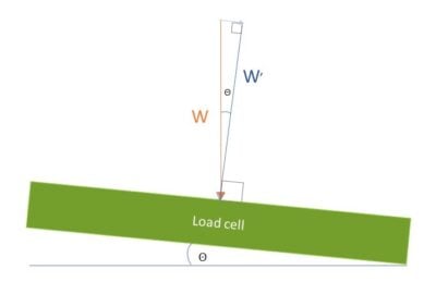
As the vectors in the figure depict, the axial component of weight, W’ will be less than the true weight, W. If the angle offset from horizontal is known (Θ in the figure), then the weight reading will be less than the true weight by the cosine of this angle. In other words, W’ = W x cos(Θ).
Does the temperature affect load cell calibration?
Cable resistance is a function of temperature. A temperature change on a load cell or a series of load cell cables affects the thermal characteristics. It is important that the cable resistance be the same for all load cells, including load cells in a series. Also, some load cells may have a cable length limit before error may occur.
Refer to Tacuna’s article, External Wiring in Strain Gauge Load Cells for more detailed information or contact Tacuna’s Load Measurement Consulting service for specific project recommendations.
How do I adjust the amplifier gain in my measurement system?
With any amplifier, gain adjustment should be according to the manufacturer’s instructions. That said, the main objective is to increase the output of the load cell, knowing its sensitivity, such that the output of the amplifier stays within a range that is acceptable by the display or data storage device interpreting the load cell reading. Moreover, the amplifier output signal offset should be centered at a nominal voltage such that the span of voltages stays within this acceptable limit but, also has a maximum value. For example, if a load cell measures both tension and compression, the signal offset should be set in the middle of the possible output voltage span of the device, whereas if the load cell only measures strain in one direction, the offset should be at one end of the span or the other depending on the polarity of the output signal.
For a specific example, we can look at the Tacuna EMBSGB200 v.2.3. This amplifier, unlike most other indicators or amplifiers, comes with a factory gain calibration. The amplifier’s gain is configurable via a DIP switch to discrete levels. The amplifier offset is adjusted manually via a potentiometer in the M version of the device, or programed in the X version. These features allow the end user to combine this amplifier to interface with the consumer’s microprocessor, analog-to-digital converter (ADC), or programmable logic controller (PLC) and begin measurement without calibrating the amplifier.
Note this device provides a 0-5V range output. Therefore, if the attached load cell measures both tension and compression, the offset should be adjusted to 2.5V; if the load cell measures just one direction of stress, the offset should be adjusted to around 0.5V or 4.5V, depending on the output polarity of the load cell. Keeping the offset at 0.5V from either limit avoids output saturation, but also improves resolution by maximizing the span.
For most other amplifiers, the gain is fully adjustable and therefore requires calibration. This happens by adjusting both the tare and maximum weights as follows: (1) load the properly connected measuring system with only tare weights such as any safety mounts or cables, and set the zero adjustment to the minimum voltage or amperage recommended by the manufacturer such that the display or data collection device reads “0”; (2) load the measuring system with the maximum weight and set the gain adjustment to the maximum voltage or amperage recommended by the manufacturer. Often these steps must be repeated to ensure proper calibration. The ANYLOAD A1A amplifier operates in this manner.
Refer to Tacuna’s article, Why Do I Need a Load Cell Amplifier (and Other Signal Conditioners)? for more detailed information or contact Tacuna’s Load Measurement Consulting service for specific project recommendations.
Load Measurement System Safety FAQ
What are the main safety concerns when designing a measuring system?
Load cells are often integral parts of large industrial or construction systems designed to keep weights or stresses within acceptable limits or to dispense commodities for commercial purposes. These environments can pose significant hazards to people and property.
The most common hazards are fire and failure of support structures.
What are some forces other than the measured load that may cause my load cells to exceed the safe load limit?
As stated before, the safe load limit corresponds to the load at which the strain gauge will undergo permanent deformation. Therefore, when engineering the load-bearing system, the system designer should calculate a maximum force (that is, the axial component relative to the loading platform) for each of the possible factors below that may affect the system in its environment, before choosing the appropriate load cell:
- Wind
- Shock loading
- Thermal expansion of materials
- Excessive vibration
For example, if the safe load limit is in the range of 300% rated capacity, the above forces’ cumulative axial effect should not exceed twice the maximum application load.
Contact Tacuna’s Load Measurement Consulting service for specific project guidance.
Load Measurement in Industry FAQ
Why should I use an electronic weighing system in my production process?
The short answer is that it enables real-time data collection, greatly adding efficiency to an industrial process. Specifically, there are three main advantages to using an electronic weighing system in production:
- Reduced Labor Costs: Manual labor to inspect material quantities in storage and in-process is time-consuming, but an electronic weighing system automatically reports material levels in tanks, solos, bins, and hoppers.
- Reduced Inventory Cost: Inventory presents a cost to a company. The electronic reporting capability of a weighing system improves accuracy and consistency in inventory tracking; this in turn reduces the need for stored raw materials and warehouse space. For example, using electronic weighing, a company can track exact quantities of a raw material by weight as it is inventoried. It can order material upon reaching a minimum threshold of supply, instead of at regular time intervals, relying on sales estimates in that interval as a basis for inventory planning.
- Efficient Quality Control: By incorporating electronic weighing systems in production lines (such as food processing), control systems can detect in real time under or over-filled vessels, potential foreign objects in packaging, and other weight-related quality issues, and help avoid compliance issues with sell-by-weight regulations.
Other advantages exist, but all point to the same underlying motivation for electronic weighing — increased efficiency, which translates to greater pricing flexibility and increased margins.
Can load cells be used near MRI machines?
Standard load cells are not suitable for MRI environments because they are typically made of ferromagnetic materials (like alloy steel). Beyond the physical safety risks of improper anchoring, load cells and MRI machines create a reciprocal interference. That is, standard load cells will create artifacts in the MRI images. Likewise, the magnet will create EMI noise in the load cell output signal, leading to inaccurate weight data.
However, special load cells do exist for medical imaging use. We partner with ANYLOAD to provide these custom-engineered, non-magnetic load cells. They are built using specialized non-ferrous materials and enhanced shielding for both patient safety and signal precision in MRI environments. The feasibility of these custom load cells depends on the following:
- Installation: To ensure accuracy and safety, the load cell must be properly shielded and professionally anchored in compliance with the facility’s safety protocols.
- Field Strength: The magnet’s strength (e.g., 1.5T or 3.0T) will dictate both the material requirements for the load cell and its minimum safe distance from the magnetic field’s center.
- Artifact Testing: Even non-magnetic metals can cause image distortion; therefore, a qualified biomedical engineer should model the load cell’s use and verify its appropriateness.
Load Measurement Calculations FAQ
How do I calculate the load cell sensitivity if a factory-calibrated value is not given?
If the load cell is not factory calibrated, it can be field calibrated to determine the sensitivity, following these steps:
- Record the no-load output voltage of the load cell,
- Load the cell with a known load,
- Record the output voltage with the known load.
- Subtract the zero output voltage from the known load voltage and use the resulting voltage as the calibration factor:
\begin{equation*}
\displaystyle S = \frac{L_{tot}(V_l-V_0)}{V_e L_{cal}A}
\label{eq:CalibrationFactor}
\end{equation*}
where
\begin{align*}
S &= \text{load cell sensitivity (mV/V)}\\
L_{tot} &= \text{the total rated capacity of the cell (Kg, Lb, N, etc.)}\\
V_l &= \text{known load output voltage (mV)}\\
V_0 &= \text{no-load output voltage (mV)}\\
V_e &= \text{excitation voltage (V)}\\
L_{cal} &= \text{known load (Kg, Lb, N, etc.)}\\
A &= \text{amplifier gain (V/V)}\\
\end{align*}
The units for the known load and total rated capacity should match and thus cancel out.
How do I convert load cell output voltage to pounds or kilograms or Newtons?
As mentioned above, each load cell should come with a calibration certificate denoting its sensitivity. using this value, one can convert the load cell’s output signal to units of weight or force. To calculate the raw output voltage of the cell relative to its rated full capacity, use the following equation:
\begin{equation}
V_{out, max}=S V_e
\label{eq:SimpleSensitivity}
\end{equation}
where
\begin{align*}
V_{out, max} &= \text{output voltage from load cell when loaded to 100% of rated capacity (mV)}\\
S &=\text{sensitivity (mV/V)}\\
V_e &= \text{excitation voltage (V)}\\
\end{align*}
Typically, load cells connect to amplifiers to transform the small output voltage to a voltage that is easily measurable (while conditioning the signal with filters, etc.). If we add an amplifier to the mix, the top equation above changes to:
\begin{equation}
V_{out, max}=S V_e A
\label{eq:AmplifiedSensitivity}
\end{equation}
where
\begin{align*}
V_{out, max} &= \text{output voltage from load cell when loaded to 100% of rated capacity (mV)}\\
S &= \text{sensitivity (mV/V)}\\
V_e &= \text{excitation voltage (V)}\\
A &= \text{amplifier gain (V/V)}\\
\end{align*}
If we were to convert this output voltage to force or weight, we would use the ratio of the actual output voltage to the maximum output voltage which is equal to the ratio of the actual load to the maximum rated load:
\begin{equation}
\displaystyle \frac{V_{out}}{V_{out, max}}=\frac{L}{L_{tot}}
\end{equation}
or
\begin{equation}
\displaystyle \frac{V_{out}}{S V_e A}=\frac{L}{L_{tot}}
\end{equation}
Rearranging, we can solve for L:
\begin{equation}
\displaystyle L=\frac{L_{tot}V_{out}}{S V_e A}
\label{eq:LoadSensitivity}
\end{equation}
where
\begin{align*}
L &= \text{load on cell (Kg, Lb, N, etc.)}\\
L_{tot} &= \text{total rated capacity of the load cell (Kg, Lb, N, etc.)}\\
V_{out} &= \text{output voltage from load cell when loaded (mV)}\\
S &= \text{sensitivity (mV/V)}\\
V_e &= \text{excitation voltage (V)}\\
A &= \text{amplifier gain (V/V)}\\
\end{align*}