As we saw in our article, Continuum Robots and Tactile Sensors, the medical industry is making great strides with the help of robotics. In that post, we introduced the idea of tactile sensors. We also presented how machine learning algorithms allow these sensors to gather shape, weight stiffness and friction coefficient data. This in turn allows the sensor-equipped robots to respond appropriately to the objects they handle.
Developing the surface materials for these tactile sensors is a science itself. This is where research of Lieutenant Colonel Brodie Hoyer comes into play. While at the Advanced Medical Technologies Laboratory and working with the Nonlinear Mechanics Lab at the University of Colorado, he and his advisors created a device to test the adhesive contact properties of materials intended for, among other things, medical robotics.
The Problem to be Studied: Soft-Tribology with Thin Membranes
The field of study for understanding the contact dynamics of two surfaces is known as tribology. Tribology studies with soft, tissue-like materials are more specifically categorized as soft-tribology. Brodie’s research involved creating such a soft-tribometric device.
The Tribology Problem:
New models are necessary to predict the contact properties of thin membranes
Thin membranes are outside the scope of traditional tribology predictive models
A new device is needed to test these properties
Specifically, Brodie wanted to improve the ability to study rolling contact mechanics between textured surfaces and soft tissue-like materials such as those found in the body. This would allow scientists to model and predict the friction, wear, and adhesion between the two materials. This in turn could contribute to the design of a range of products including medical robotics, bandage adhesives, and wearable medical devices.
The first challenge was to create a mathematical model to predict the tested material’s behavior. Older models for contact between surfaces addressed in Brodie’s research apply mostly to more rigid materials. That is, they don’t account for the stretching or adhesion of soft membranes. These thin membranes are often used as contact surfaces in tactile sensors.
Also, these previous models (first Hertz, then Johnson, Kendall and Roberts) describe simple indentation contact and not rolling contact. Brodie’s research hypothesized that using a roller to apply force and make contact across a soft material would give the ability to both control and account for the soft material’s stretching. This would be the case even if the material stretches or otherwise behaves differently when frictional forces act upon it along different directions.
The Mathematical Models to Predict Thin Membrane Adhesion
First, Brodie used these previous models of forces and deformation in contact theory to describe the behavior of a rolling indenter over a flat polydimethylsiloxame (PDMS) substrate. PDMS is a type of silicone with certain physical properties that are similar to biological tissue. It is also optically clear, making it possible to photograph the contact between it and the indenter. (If you’ve seen soft contact lenses, you’ve probably seen PDMS!)
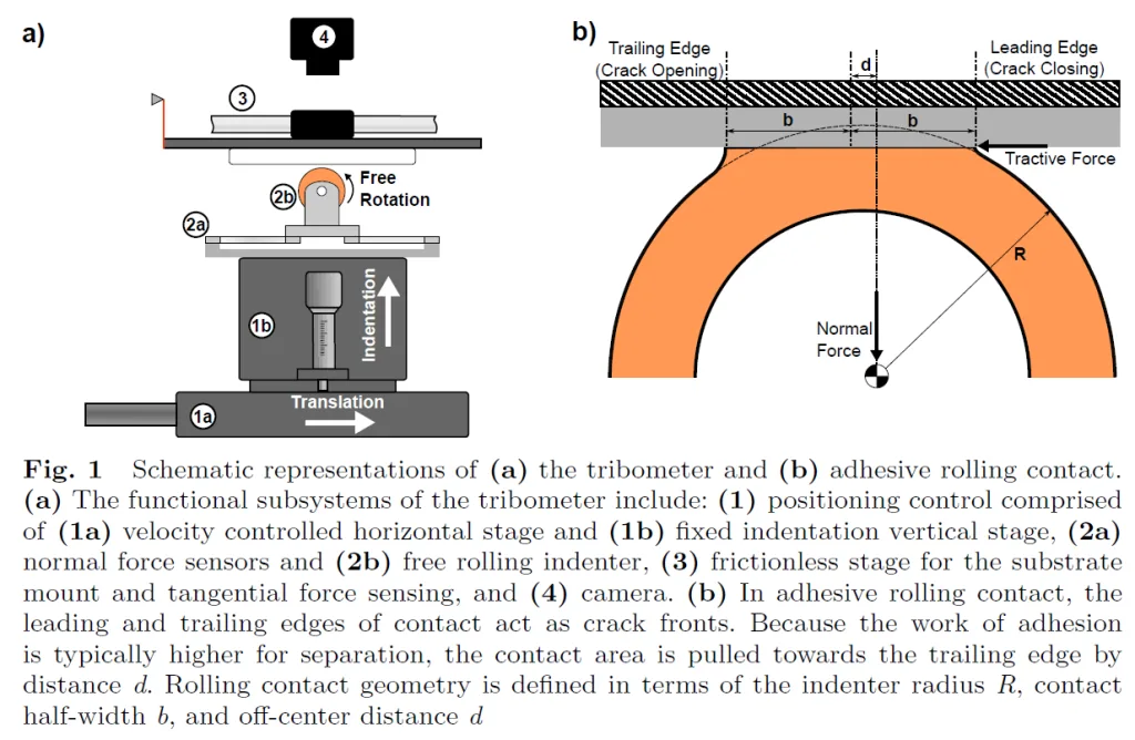
He started with these earlier models, describing the contact behavior of a static cylinder indenter. These models define “crack fronts” as the interfaces where the two contact materials adhere or separate. They assume the crack fronts are equidistant from the center axis of the cylinder. (See Figure 1(b) below, from the original research paper.) These models also assume the cylinder’s adhesion to the substrate materials was the same along both crack fronts. That is, opening (indenter lifting) and closing (indenter compressing) require equal work.
By contrast, Brodie’s model needed to account for the behavior of a soft material of finite thickness rolling over the substrate. In this case, the roller’s leading edge has a different work of adhesion along the leading (closing) edge or crack front than on the trailing (opening) edge. Therefore, these crack fronts are no longer equidistant from the center axis of the roller. Instead, because of the higher work of adhesion at the roller’s trailing edge, the leading-edge crack front is a shorter distance from the roller’s center axis. Brodie’s laboratory setup was designed to verify and quantify this behavior.
By starting with traditional adhesion models, assuming a cylindrical indenter and taking into account the different behavior of a rolling indenter and soft materials, Brodie derived the relationship between the tractive force (traction) between the two surfaces (the one on the roller and the one on the flat surface) to be the difference between the work of separation at the trailing edge of the roller and the work of adhesion at its leading edge. The specifics can be found in his research paper, at this link.

The Indenter Design
The contact indenter design for this experiment had three directions of movement, or three degrees of freedom. (See Figure 1 (a) above)The first direction was vertical displacement. This action would compress the indenter toward, or release it from, the flat substrate material (labeled “Indentation” in Figure 1(a)). The second was a horizontal movement that would push the base of the roller forward (“Translation” in Figure 1(a)). The third motion was the rolling action itself. To isolate forces in each direction, the flat surface mount included frictionless air bearings. This prevented the transfer of normal loads to the load cells measuring tangential forces. It also eliminated friction that could alter tractive force measurements.
Multiple load cells captured both tangential and normal forces at various positions in the structure. Brodie also mounted a camera above the contact surfaces to visually capture the leading and trailing contact edges. This allowed him to confirm his theories of the contact width and difference of these two edges’ distance from the roller’s center axis. Knowing the roller’s exact vertical and horizontal position when measuring these widths was essential. Therefore, each image had a timestamp to match the roller’s exact position with each visual measurement.
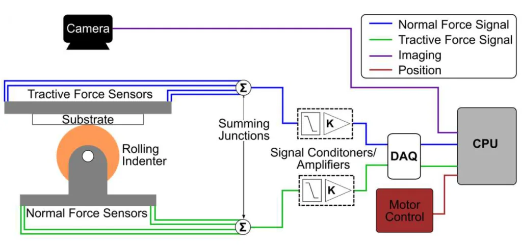
For each force direction, a junction box electrically combined load cell measurements. Signals from each junction box passed through a Tacuna Systems EMBSGB200 amplifier to a data acquisition system and collected by a MATLAB script. This is pictured in Figure 2.

The Experiment: Verifying the Device, Then Testing Soft Membranes
Brodie’s experiment involved two test cases. The first case tested the device’s behavior against previous models (Johnson, Kendall and Roberts) to prove it would behave as expected. This test case therefore used a rigid acrylic indenter rolling along a flat, relatively rigid elastomer substrate.
The second test case studied the roller’s adhesion when covered with a soft membrane. This test case used the same flat substrate as the first. However, instead of the rigid indenter, this case used one with a rigid core thermally bonded to a cover of a 3mm highly deformable viscoelastic elastomer. This setup would give insight not only to the contact behavior from the material’s viscoelasticity, but also from its thickness.
Results
His first test case did its job. That is it proved the data output from his tribometric device would produce data results that were in close agreement to predictive models. This proved the device was valid for testing contact behavior between two materials. To keep this article simple, we will point to the results of this test case, found here.
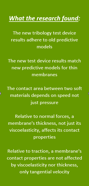
In the second test case, the data was able to validate new predictive models in thin flexible membranes that the previous mathematical models could not. In the first place, data showed that as the contact half-width approached the thickness of the membrane, previous predictive models deviated greatly from the actual behavior of the material. That is, a much greater normal force was needed to create the same contact half-width than older models would predict. However, the new predictive model created as part of this research did agree very closely with the experimental data.
This second test case also showed that the roller’s translational velocity affected the contact half width relative to the applied normal force. That is, the faster the roller moved over the substrate, the larger the contact half with became, even if the roller was operating with the same depth of indent.
These first two findings of the second test case indicate that when testing a membrane’s contact properties relative to normal forces, the experimenter needs to take into account the membrane’s viscoelasticity AND its thickness. Yet this was not the case with the tractive forces. Interestingly, the material’s viscoelastic properties did not significantly affect its traction. Tractive force behaved consistently as a function of tangential velocity regardless of how deep the indenter pressed on the substrate. Therefore, Brodie concluded that this measurement could reliably predict the adhesion between a membrane and the PDMS substrate.

What’s Next?
This research provides a basis for further study of the contact mechanics of membranes. Of course, we at Tacuna Systems are happy we were able to help with the reliable data collection involved with this experiment. And this review would indicate that Brodie Hoyer was happy we could help as well!


