
Our article, Load Cells and Force Sensors in Robotics, introduces recent advancements in robotics technology through the use of load cells and force transducers. Here we continue by looking at a specific example of robotics that employs these sensors: continuum robots.
Key Takeaways
- Continuum Robot Dynamics: Flexible, continuously curving manipulators navigate confined, high-risk environments like surgical pathways, hazardous pipe networks, and restricted industrial machinery.
- Sensor Selection & Placement: Micro-scale tactile arrays measure contact forces at the flexible tip, while strain-gauge miniature load buttons and torque transducers manage tendon-drive cable tension and motor torque at the actuator base.
- Multi-Axis Force/Torque Sensing: Tactile sensors quantify multi-directional vectors (\(F_x, F_y, F_z\)) and rotational moments (\(M_x, M_y, M_z\)) simultaneously, preventing structural or tissue damage during delicate contact.
- AI & Vision-Tactile Integration: Optoelectronic matrix arrays combined with multimodal AI models enable real-time slip detection and autonomous surface mapping without requiring pre-programmed object geometries.
What is a Continuum Robot?
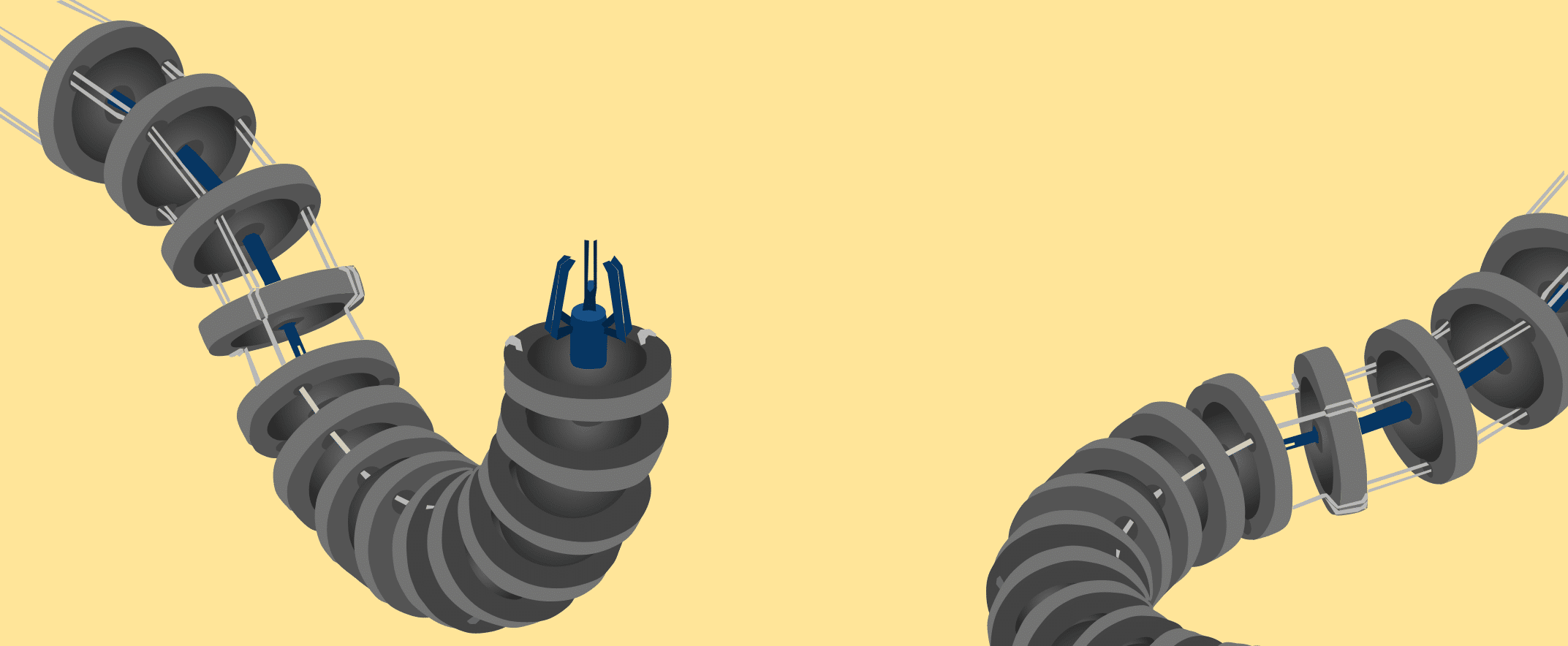
A continuum robot is a continuously curving manipulator like the arm of an octopus or the trunk of an elephant but at a much smaller scale. It is incredibly maneuverable in navigating restricted spaces without doing damage to the passage walls, materials, or tissue. Also, it may have devices attached to its end, such as a camera, grasping claw, or a cutting mechanism.[1] Some typical applications of a continuum robot are:
- Robotic surgery procedures such as endoscopy, colonoscopy, or neurosurgery;
- Hazardous operations such as bomb disposal or search and rescue at natural disaster sites;
- Actions in hazardous atmospheres such as a nuclear site;
- Maintenance applications in industrial situations where space is restricted;
- Transport mechanisms for inserting embedded sensors such as load sensors, force sensors, or tactile sensors.
Tactile Sensors vs. Other Force Transducers
Load cells/strain gauge sensors, piezoelectric force sensors, and tactile sensors have much in common. All of these sensors perform the same function of measuring force. However, they differ in the types of applications where they best serve.
The following sections quickly explain the functions of different sensors and their applications in robotics.
Load Cells/Strain Gauge Sensors
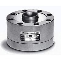
Load cells and strain gauge sensors represent the most mature, reliable technology for force measurement. They convert mechanical force into a proportional electrical signal via strain gauges bonded to an internal flexure. While conventional disk or canister load cells (Figure 1) are too bulky to mount directly on the micro-scale tip of a flexible continuum arm, strain gauge technology remains critical to the system’s drive mechanism. Modern continuum robots rely on miniature load buttons to monitor tendon tension, compact multi-axis load cells at structural anchor points to capture multi-directional sway, and torque transducers at the motor base to evaluate rotational forces.
Piezoelectric Force Sensors
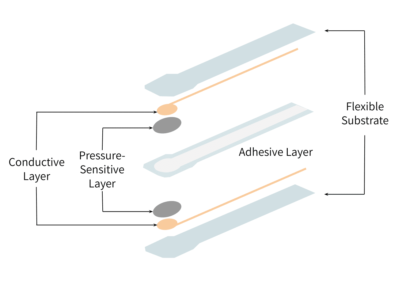
A piezoelectric force sensor (Figure 2) generates an electrical charge directly in response to mechanical stress without requiring an external excitation voltage. Piezoelectric elements are thin, lightweight, and highly responsive, making them popular for high-frequency dynamic impact testing and embedded monitoring in rigid industrial end-effectors. However, because their electrostatic charge decays over time, piezoelectric sensors suffer from signal drift during sustained contact and cannot measure static loads. For continuous tendon tensioning or static holding force applications, strain-gauge-based sensors remain the preferred choice. (See Comparing Strain Gauges to Piezoelectric Sensors.)
Tactile Sensors
Unlike single-axis force transducers, tactile force/torque sensors and multi-axis load cells measure multi-directional contact forces (\(F_x, F_y, F_z\)) and rotational moments (\(M_x, M_y, M_z\)) simultaneously. While flexible tactile arrays handle distributed contact along the arm, rigid joint linkages and mounting bases utilize packaged multi-vector sensors (see our guide, Multi-Axis Load Cells Explained) to capture total system loads.
This multi-axis feedback is vital for delicate, compliant tasks (such as endoscopic surgical maneuvers or navigating hazardous pipeline geometry) where unmeasured shear or twisting forces could damage surrounding tissue or structural walls [2]. Modern continuum manipulators rely on tactile feedback for closed-loop force control, adjusting grasper pressure and segment curvature in real time to secure objects without causing permanent deformation.
Advances in Tactile Sensor Design
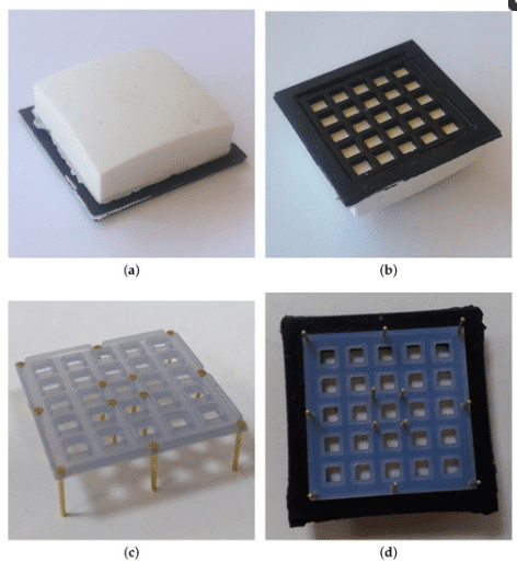
Recent breakthroughs in vision-tactile sensing and multimodal AI have transformed how continuum robots interact with unstructured environments. Rather than requiring pre-programmed object geometries, modern tactile systems utilize micro-optoelectronic arrays embedded beneath deformable elastomer skins to handle unknown, delicate objects autonomously.
Key technological advances include:
- Optoelectronic Matrix Arrays: Internal micro-cameras or photodiode grids capture microscopic deformations of a soft silicone cap (Figures 3 and 4), converting optical displacement into high-resolution surface vector maps.
- Real-Time Slip & Shear Detection: High-speed signal processing evaluates localized micro-displacements at kilohertz rates, detecting shear stress and incipient slip before an object slides out of a manipulator’s grip.
- Multimodal Foundation Models: AI control models fuse camera feeds with real-time tactile data, allowing the robot to instantly infer object stiffness, weight, and friction coefficients during contact.
- Contact Surface Characterization: High-sensitivity tactile skins are tested and calibrated against precision miniature strain gauge load cells to benchmark contact force profiles on soft biological tissues and synthetic elastomers. See our customer case study, Measuring Contact Forces on Soft Materials for Medical Robotics and Other Applications, to further understand modeling of contact surfaces.
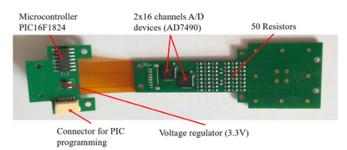
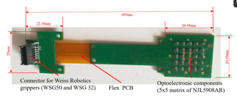
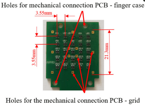
Figure 3: Three Views of a Tactile Sensor PCB
A Comparison Table of Continuum Robot-Driving Sensors
| Sensor Feature / Metric | Sensor Type | ||
|---|---|---|---|
| Strain Gauge Load Cells | Piezoelectric Sensors | Tactile Force/Torque Sensors | |
| Primary Measurement | Static & dynamic axial force | Dynamic force & high-frequency impact | Distributed contact force & torsional moments |
| Excitation Required | Yes (5–10 VDC) | No (self-generating charge) | Yes (integrated PCB / optoelectronic) |
| Static Load Drift | None (ideal for long-term load) | High (charge decays over time) | Low to moderate |
| Typical Robotic Placement | Tendon drive bases, joint linkages | Impact end-effectors, dynamic grippers | Soft continuum fingertips, dexterous manipulators |
| Relative Size | Miniature to heavy industrial | Ultra-thin, low-profile | Micro-scale flexible arrays |
References
[1] Costanzo, Marco (2019), Design and Calibration of a Force/Tactile Sensor for Dexterous Manipulation, Sensors 19(4), pp 966, https://doi.org/10.3390/s19040966 ; https://www.mdpi.com/1424-8220/19/4/966/htm
[2] Mahvash, Mohsen (2011), Stiffness Control of Surgical Continuum Manipulators, IEEE Transactions on Robotics pp 334-346, DOI 10.1109/TRO.2011.2105410