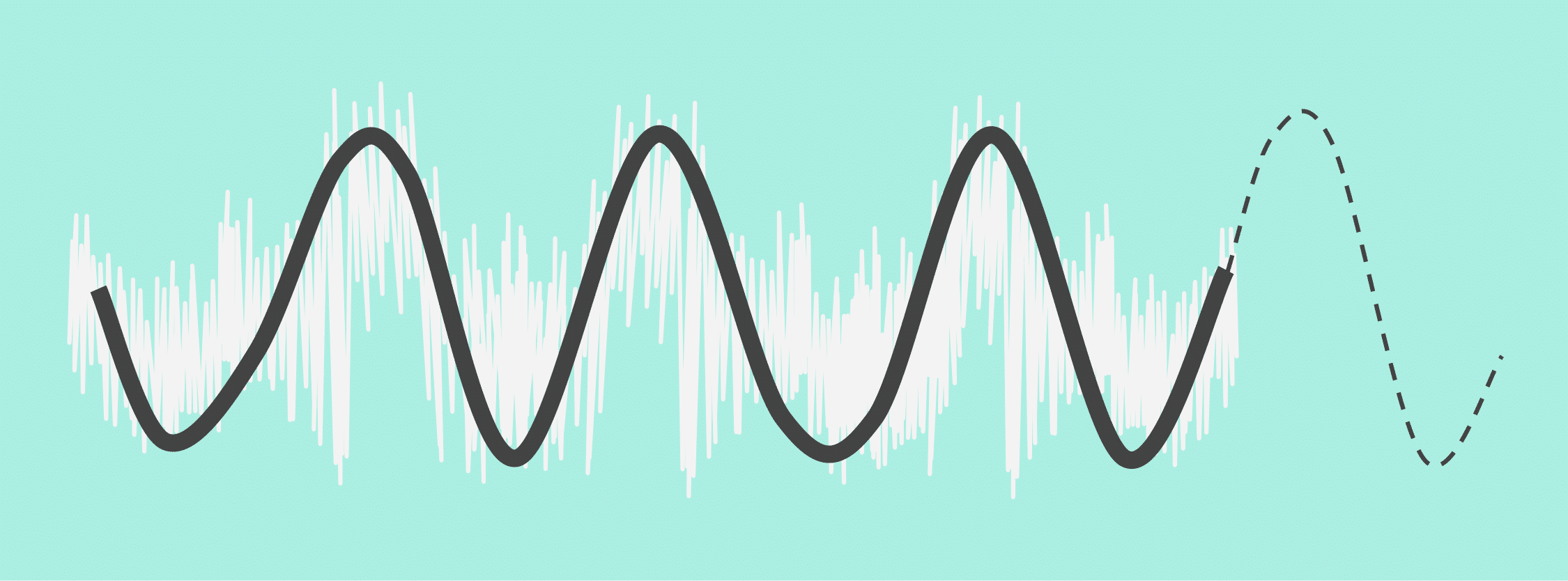
Load cells produce very small voltages, on the order of millivolts, when measuring a force. Consequently, any unwanted voltage in the load cell output, such as that induced by environmental interference, creates error in the measurement. Therefore, when making very sensitive load cell measurements it’s imperative to reduce the effects of environmental noise as much as possible. This article contains some best practices for reducing the effects of electrostatic and electromagnetic noise in load cell output signals.
Sources of Noise
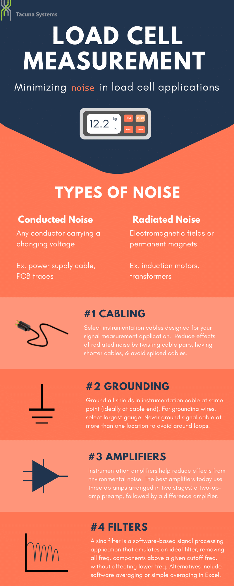
Almost every electronic device emanates some kind of electrical power which can induce noise in a load cell circuit. This obviously has an impact on its measurement accuracy. To simplify, there are two general categories of this induced noise: conducted noise and radiated noise.
Conducted noise enters load cell circuitry through capacitive coupling. It is the result of an electrostatic field generated by a changing voltage. Therefore, any conductor carrying a changing voltage has the potential (no pun intended) to introduce conducted noise into the system. This includes everything from power supply cables to printed circuit board (PCB) traces. Since capacitance increases with proximity, the closer the noise source, the higher the capacitance and the greater the conducted noise.
Radiated noise is the result of alternating electromagnetic fields or permanent magnets. The signal wires in load cell applications act as antennas for this radiated noise. Similar to conducted noise, the closer the magnetic field is to the signal wires, the greater the noise will be. So, items like motors and transformers, which produce relatively strong magnetic fields, need to be considered when eliminating noise from the environment.
Best Practices for Minimizing Noise in Load Cell Applications
Cabling
Perhaps the single most important decision you can make to eliminate noise is the cable you choose for the signals in the load cell circuit. If you can get your hands on it, use instrumentation cable specifically designed for these types of applications. Since you need to transport two signals, the excitation voltage and the output signal, you’ll need two pairs of wires. Each pair must be twisted to reduce coupling capacitance. If the wires are untwisted, using a drill can manually create an unshielded twisted pair (UTP). Ideally, you’d like each wire in the UTP wrapped in its own shield to reduce the effects of cross talk between the cables. However, this isn’t always possible. At the very least, you’ll want to have both UTP wires shielded together to reduce effects from radiated noise.
All cables in a load cell circuit should be kept as short as possible to minimize noise induction. If you can, avoid using a spliced cable, as the splice junction is an opportunity for noise to enter the system. If you do have to splice cables in the field, be sure to keep the shield/drain wire intact and solder or secure screw/crimp the splice. You may also want to consider using a cable splicing kit.
Grounding
If cable choice is the most important decision, then system grounding comes right after it. In this case, grounding includes both signal cables and power cords. For starters, you’ll want to ground all of the shields in the instrumentation cable at the same point, ideally at the instrumentation end of the cable. If you use grounding wires, use the largest gauge possible and keep them as short as possible. And never ground the signal cable at more than one location. That creates the opportunity for ground loops. In the event you have unused conductors in a signal cable, don’t leave them disconnected because they’ll act like antennas. Be sure to ground the signal conductors and any shield around them. With respect to power cable grounding, plug all the signal-handling equipment into a single power strip if you can. That way all the equipment will use a common ground.
Amplifiers
All load cell measurements require the use of an instrumentation amplifier. The best instrumentation amplifiers today use three operational amplifiers (op amps) arranged in two stages: a two-op-amp preamp, followed by a difference amplifier. Instrumentation amplifiers can actually help reduce the effects from noise in the environment. Noise on the two signal wires is proportional to how close the two wires are. Twisted wires are very close, which means the noise signals on both wires are identical. This is an important property used by amplifiers to eliminate the noise through common-mode rejection.
Filters
The best type of load cell noise filter for this application is known as a sinc filter. This is a software-based signal processing application that emulates an ideal filter. It removes all frequency components above a given cutoff frequency without affecting lower frequencies. Unfortunately, this is not a DIY filter. However, there are some alternatives such as software averaging or simple averaging in Excel.
Other Considerations
What bridge configuration should you use to minimize the impacts of environmental noise?
The full bridge is the optimal choice, and the one that quality load cells employ. With this configuration, all four branches of the bridge are occupied by nearly identical gauges. The result is better common-mode rejection and higher signal-to-noise ratio (SNR). If a full bridge is unavailable, the viable alternatives are (in order of effectiveness): a 3/4 bridge, a half bridge and finally a quarter bridge with a 3-wire setup.
What physical configurations can you implement?
In a very noisy environment, it’s a good idea to cover strain gauges and lead wires with aluminum or tin-plated copper foil to shield them from radiated noise. If you do use a foil shield, you’ll want to ground it where you ground the signal shields. Also make sure you don’t short out the solder joints by first coating them in sealant or with rubber, Teflon or Kapton tape. Always do your best to move electronic and radiating devices as far away as possible from the measurement circuit. This includes items such as fluorescent light bulbs, WiFi routers and even soldering irons. Finally, if you’re using magnetic shields to protect the system from radiated signals, make sure you use specially-designed, high-permeability alloys (e.g., mu-metal®) that have been developed specifically for magnetic shielding.
Conclusion
Noise is present in most if not all environments where load cells operate and it affects their measurement accuracy. This article introduces ways to minimize its impact through proper cabling, grounding, and shielding techniques. Likewise signal conditioners such as amplifiers can further enhance signals. Finally, the possibility exists that the load cell may be bad. For more information on these topics, refer to the following documents in Tacuna Systems’ Knowledge Base:


