
Even premium, quality load cells encounter operational faults over time that disrupt weighing system performance. This comprehensive troubleshooting guide explains common sensor failures and gives a step-by-step diagnostic framework to isolate and resolve them.
Key Takeaways
- Common Failure Modes: Load cell malfunctions typically manifest as sudden zero balance shifts, erratic readouts, or complete signal loss.
- Visual Triage First: Preliminary visual inspections isolate external mechanical interference, binding, and cabling damage before disconnecting any hardware.
- Essential Diagnostic Toolkit: Troubleshooting requires a high-quality digital voltmeter/ohmmeter and a low-voltage mega-ohmmeter.
- Core Diagnostic Tests: Isolate internal hardware faults by verifying the zero balance baseline, testing insulation resistance, checking bridge symmetry, and measuring shock resistance.
- Factory Recertification: If a load cell fails any internal electrical checks, return the component to the OEM for formal repair or replacement.
Common Load Cell Faults
When a load cell fails, the weighing system typically exhibits one of these behaviors:
- A sudden, permanent shift in the system’s baseline zero balance value.
- Unstable, drifting, or random fluctuations at its zero point.
- Incorrect weight displays or immediate overload readings when applying a known test load.
- Dead systems that produce no output signal or readout display at all.
- Erratic, non-repeatable output spikes during the loading or unloading cycle.
Technicians can isolate each of these symptoms using the specific targeted electrical tests outlined below.
Troubleshooting Load Cells: A Step-by-Step Guide
If your weighing system exhibits any of the above performance faults, perform these diagnostic procedures in sequence.
1) Perform Preliminary Visual Checks
Before disconnecting its electronic components, verify the physical integrity of the weighing installation to rule out any mechanical errors:
- Inspect Mechanical Supports: Check the load cell orientation, mounting brackets, and load-directing hardware for cleanliness, levelness, and structural alignment. Debris accumulation or physical binding can mimic an electrical fault. (See Load Cell Mounting and Installation Best Practices.)
- Examine the Sensor Body: Inspect the load cell housing for dents, cracks, corrosion, or any deformation in the spring element. Placing a precision straightedge against the sensor body can help reveal subtle structural changes from wear or severe overload events. (See Quality Control: Load Cell Handling, Preservation and Storage Do’s and Don’ts.)
- Audit the Cabling Infrastructure: Verify all interconnecting cables at the summing or junction box. Ensure cabling is entirely free of structural cuts, conduit crimps, moisture exposure, or exposed shielding wires.
- Verify Indicator Connections: Inspect the secure terminal seating where the junction box connects to the digital indicator panel.
- Test the Excitation Source: Measure the incoming voltage signal to verify that it is noiseless and unfluctuating.
If these visual inspections reveal any issues, correct them immediately and retest the system. If the operational faults persist, proceed to instrument testing.
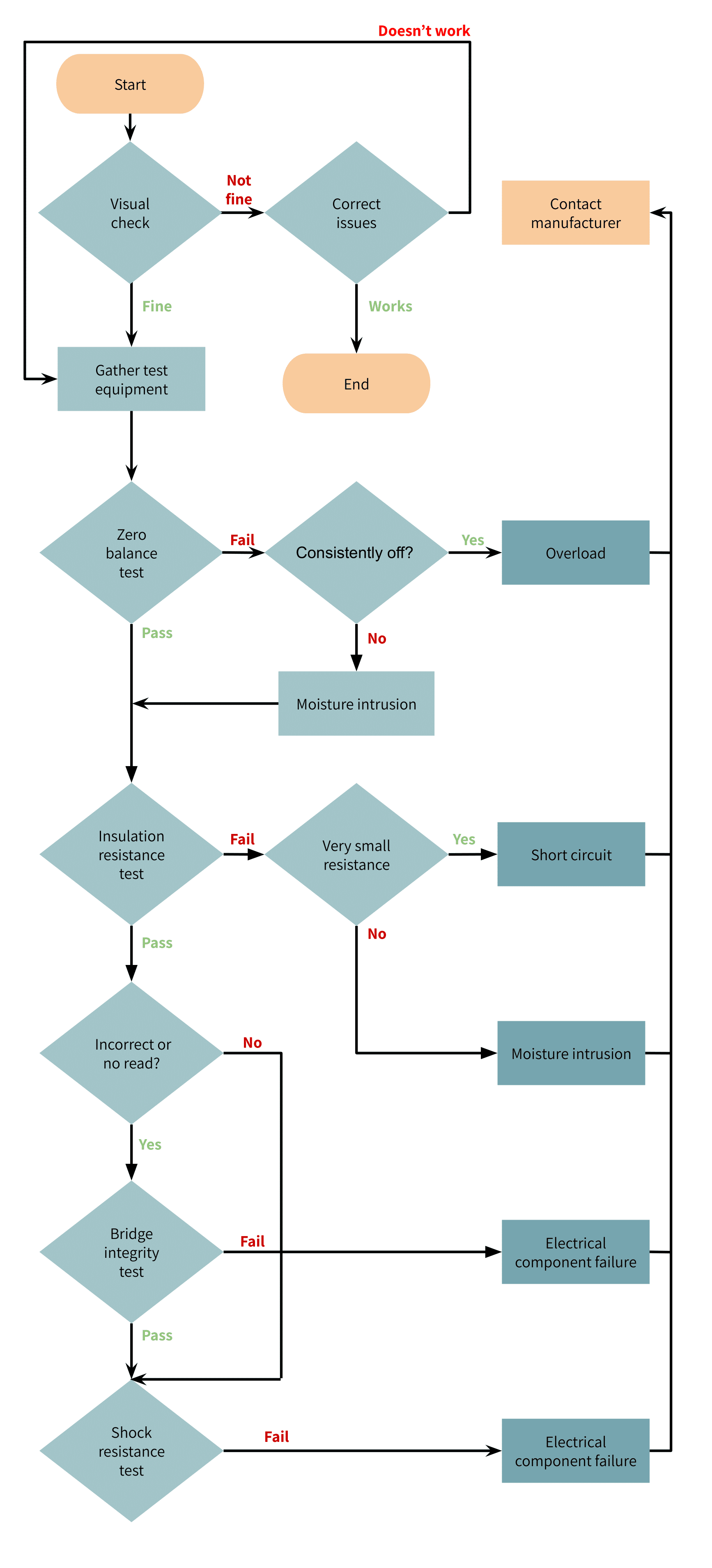
2) Gather Required Test Equipment
The remainder of the steps test the internal electronics and therefore require the following specialized equipment:
- Digital Voltmeter and Ohmmeter: A high-quality multimeter capable of measuring 0 to 50 mV (for standard passive load cells) and 4 to 20 mA (for systems utilizing amplified outputs). The meter must deliver an accuracy profile of at least ±0.1 mV and ±0.5 mA.
- Insulation Tester (Mega-Ohmmeter): A dedicated mega-ohmmeter capable of reading up to 5,000 Mega-ohms (MΩ) with an accuracy threshold of 500 MΩ.
Critical Safety Warning: The mega-ohmmeter must never supply more than 50V to the load cell circuitry. Applying insulation test voltages higher than 50V will cause immediate, permanent dielectric breakdown and destroy the internal strain gauge elements.
3) Determine the Zero Balance
The zero balance represents the unfiltered electrical output of an entirely unloaded load cell. For multi-sensor weighing systems, isolate and evaluate each load cell individually.
- Disconnect the load cell output wires from the junction box while leaving the input wires attached to a stable, low-noise excitation voltage source.
- Measure the output voltage across the positive and negative output terminals (+Signal and -Signal) using the digital millivolt meter.
- Divide the measured millivolt output by the input excitation voltage to calculate the normalized zero balance baseline in millivolts per volt (mV/V).
$$\text{Zero Balance (mV/V)} = \frac{\text{Measured Output (mV)}}{\text{Excitation Voltage (V)}}$$ - Compare your calculated baseline against the nominal zero balance value specified on the product’s factory data sheet.
Expected result: The calculated value falls within the zero-balance tolerance window specified in the manufacturer’s product data sheet.
Test failure: A sudden, persistent shift in the zero balance typically indicates that the load cell has suffered structural deformation from mechanical overload or a dynamic shock load. Conversely, a slow, continuous zero-point drift can indicate moisture intrusion inside the sensor element, which alters internal strain gauge resistance.
4) Perform an Insulation Resistance Test
Perform an insulation resistance test if the system exhibits drifting readouts or random, unstable shifts at the zero point. This checks for electrical leakage by measuring the electrical isolation between the internal circuit bridge and the external structural elements.
- Disconnect the load cell from the amplifier, summing box, and indicator panel.
- Connect all the input, output, and sense (if equipped) wires into a single electrical node.
- Measure the insulation resistance between the combined wire node and the load cell spring element body with the mega-ohmmeter.
- Then measure the insulation resistance between the combined wire node and the cable’s braided outer shield.
- Lastly, measure the insulation resistance between the load cell body and the outer cable shield.
Expected Result: The insulation resistance across all three measurements must meet or exceed the specification on the product data sheet (typically greater than 5,000 MΩ).
Test Failure: A resistance below the factory specification indicates electrical leakage from internal contamination or moisture intrusion. A critically low resistance (approaching zero ohms) reveals a short circuit to the frame, which destabilizes the load cell’s output.
5) Perform a Bridge Integrity Test
Execute a bridge integrity test if the system indicator displays an immediate overload condition, produces unrealistic readings for a known weight, or fails to give a reading. This test checks the internal Wheatstone bridge’s output resistance, input resistance, and bridge symmetry.
- Disconnect the load cell from all junction boxes and power supplies.
- Measure the input resistance directly across the input terminals (+Excitation to -Excitation) using a standard digital ohmmeter.
- Measure the output resistance directly across the output terminals (+Signal to -Signal).
- Compare the measured input and output resistance values against the nominal values listed on the product data sheet.
- Measure the resistance from the negative output lead (-Signal) to the negative input lead (-Excitation). Then, measure the resistance from the negative output lead (-Signal) to the positive input lead (+Excitation). The comparison of these two balancing legs defines your bridge balance symmetry.
Expected result: The absolute difference between the two balancing legs must be less than or equal to 1%. Additionally, the overall input and output resistances must remain within the product’s specification limits (typically under 3,000 ohms).
Test failure: Differences in the bridge balance measured values that exceed 1%, or input/output resistance(s) that exceed 3 kilo-ohms, reveal internal circuit damage. These failures commonly result from nearby lightning strikes (overvoltage spikes), extreme thermal exposure, or careless physical handling.
Warning: Never use a high-voltage mega-ohmmeter to measure input or output resistance across the bridge circuit. The test voltage will immediately bridge the strain gauge grids and permanently destroy the internal sensors.
6) Perform a Shock Resistance Test
Conduct a shock resistance test if the weighing system displays erratic readings only when a load is applied or removed.
- Connect the load cell input wires to a stable voltage source.
- Attach a high-resolution digital voltmeter to the sensor’s output terminals.
- Gently tap the load cell body with a small rubber or wooden mallet to induce a minor mechanical shock. Caution: For very low capacity load cells, take care not to overload the load cell while performing this step.
Expected Result: The voltmeter readings must not spike or behave erratically during impact. Rather, the output signal must remain stable and return immediately to the established zero baseline.
Test Failure: If the display shows erratic readings, then there could be a failed electrical connection within the load cell. Alternatively, this can indicate a compromised glue layer or bond between the strain gauge sensor and the spring element.
Quick-Reference Table: Symptoms and Diagnostic Actions for Load Cell Troubleshooting
| Observed Symptom | Potential Root Cause | Corrective Diagnostic Action |
|---|---|---|
| Sudden change or drift in the zero-balance value. | Structural deformation from mechanical overload, severe shock loads, or localized moisture intrusion. | Execute the Zero Balance Test to calculate the mV/V baseline shift. |
| Unstable, drifting, or random changes at the zero point. | Electrical leakage caused by internal moisture ingress or chemical contamination. | Execute the Insulation Resistance Test using a low-voltage mega-ohmmeter. |
| Immediate overload display, incorrect weights, or a dead reading. | Internal bridge asymmetry, short circuits, or component failure from lightning or extreme heat. | Execute the Bridge Integrity Test to measure circuit input/output resistance. |
| Erratic or spiking readouts during load application or removal. | A fractured internal electrical connection or a failing glue bond beneath the strain gauge matrix. | Execute the Shock Resistance Test by gently tapping the sensor with a mallet. |
Conclusion
If your weighing system fails any of these comprehensive diagnostic tests, its load cell’s internal circuitry or mechanical substrate is functionally defective. In this case, contact the OEM for repair or replacement.
Tacuna Systems provides technical support for its entire product portfolio. Our engineering team is available to help you isolate field faults, interpret electrical data sheet tolerances, and resolve complex application issues.