
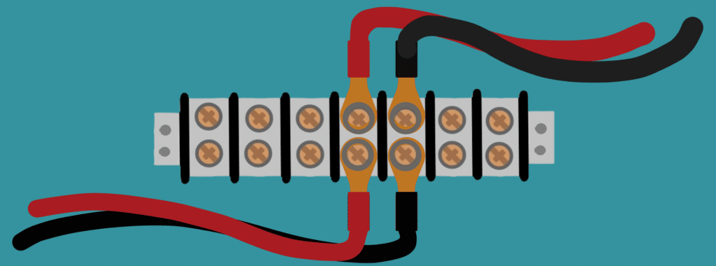
A terminal block is a modular, insulated connector housing that securely joins two or more wires using internal conductive strips and screw or spring clamps. Aside from safety, terminal blocks have distinct advantages. They neatly organize circuits since they mount to panels or boards and come in colors to help distinguish or group connections. And since they allow easy replacement of faulty devices without disturbing the rest of the circuit, they make circuit maintenance easier.
Key Takeaways
- A terminal block is a wiring connector in an insulated housing, designed to connect input and output wires securely.
- Types of terminal blocks include PCB mount, pass-through/DIN rail, and barrier strips, each suited for different applications.
- Wire clamp type determines compatibility with solid vs. stranded wire and affects vibration resistance. Screw clamps suit stranded wire, push-in clamps suit solid wire, and push-button clamps work with either.
- When choosing a terminal block, consider these key specifications: pole count, pitch, wire size, amperage rating, and voltage rating.
- Always select a terminal block with an amperage rating at least 150% of your circuit’s maximum expected current, and a voltage rating that exceeds peak operating voltage plus expected surges.
Electrical Terminal Block Types by Mounting Configuration
Terminal blocks usually fall into categories according to what they mount to, how many connections they establish, how they secure the attached wires, and their electrical specifications. The subsections below subdivide them specifically by mounting type. The subsequent sections categorize them by connectivity.
PCB Mount Blocks
These terminal blocks attach to a printed circuit board (PCB). One side secures a bare wire with a clamp or screw, while the other side has a metal peg soldered to the PCB, making only one side of the connection semi-permanent. They can establish single, dual, or multiple connections.
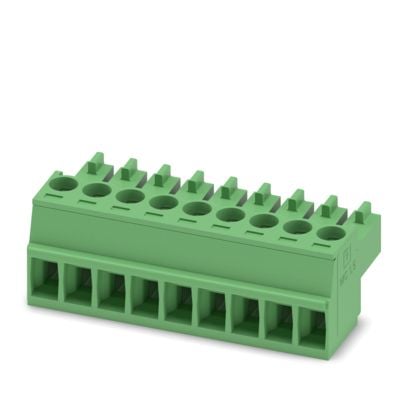
PCB terminal blocks are often sold in detachable (plug-in) configurations, allowing the PCB to be removed from the circuit without disturbing field wiring. This significantly improves maintenance efficiency.
DIN-Rail and Pass-Through Terminals
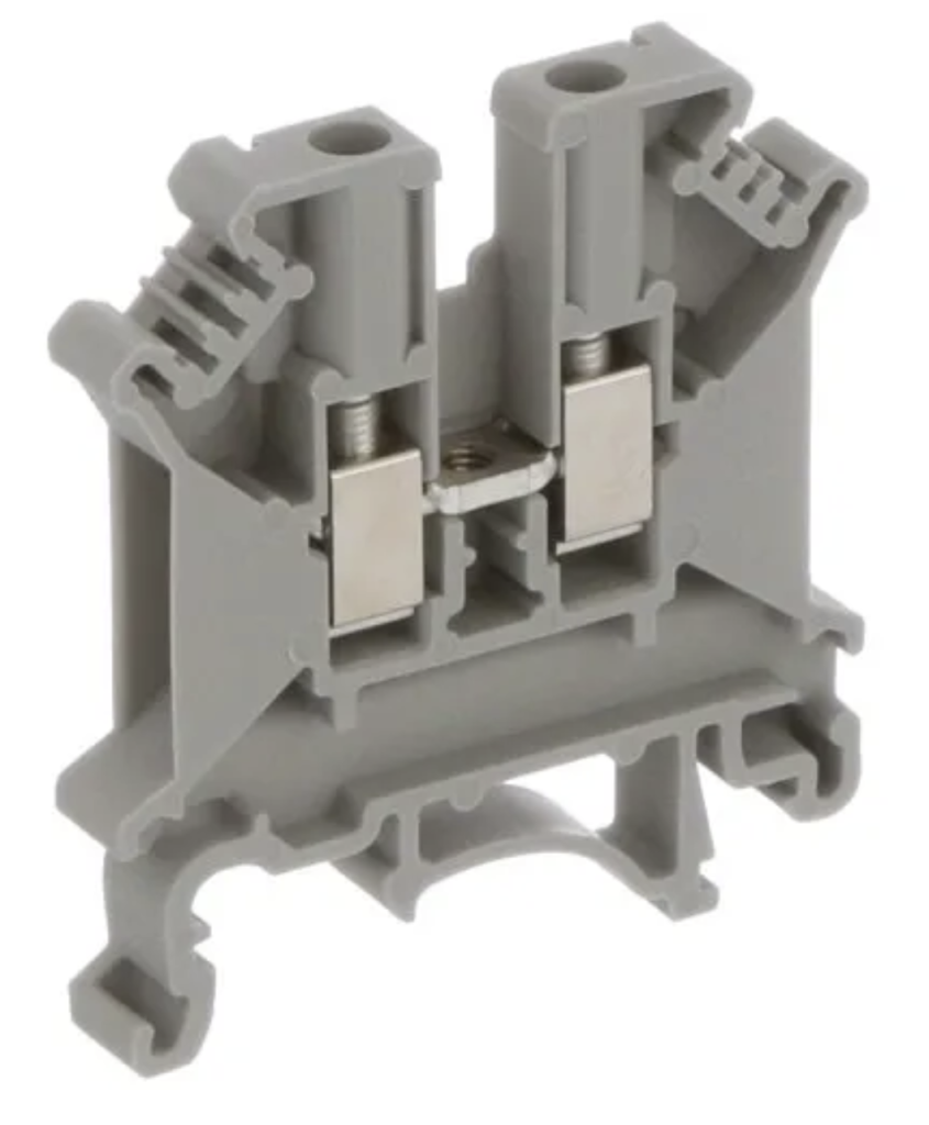
As the name implies, these terminal blocks have a housing shaped for mounting on a DIN rail. Like the PCB-mount type, they may have single, dual, or multiple levels, each level connecting one input to one output (hence, “pass-through”).
DIN rail terminal block housings typically have slots for each input opposite the slots for outputs. A clamp or screw secures each bare wire end within each slot.
Barrier Strips
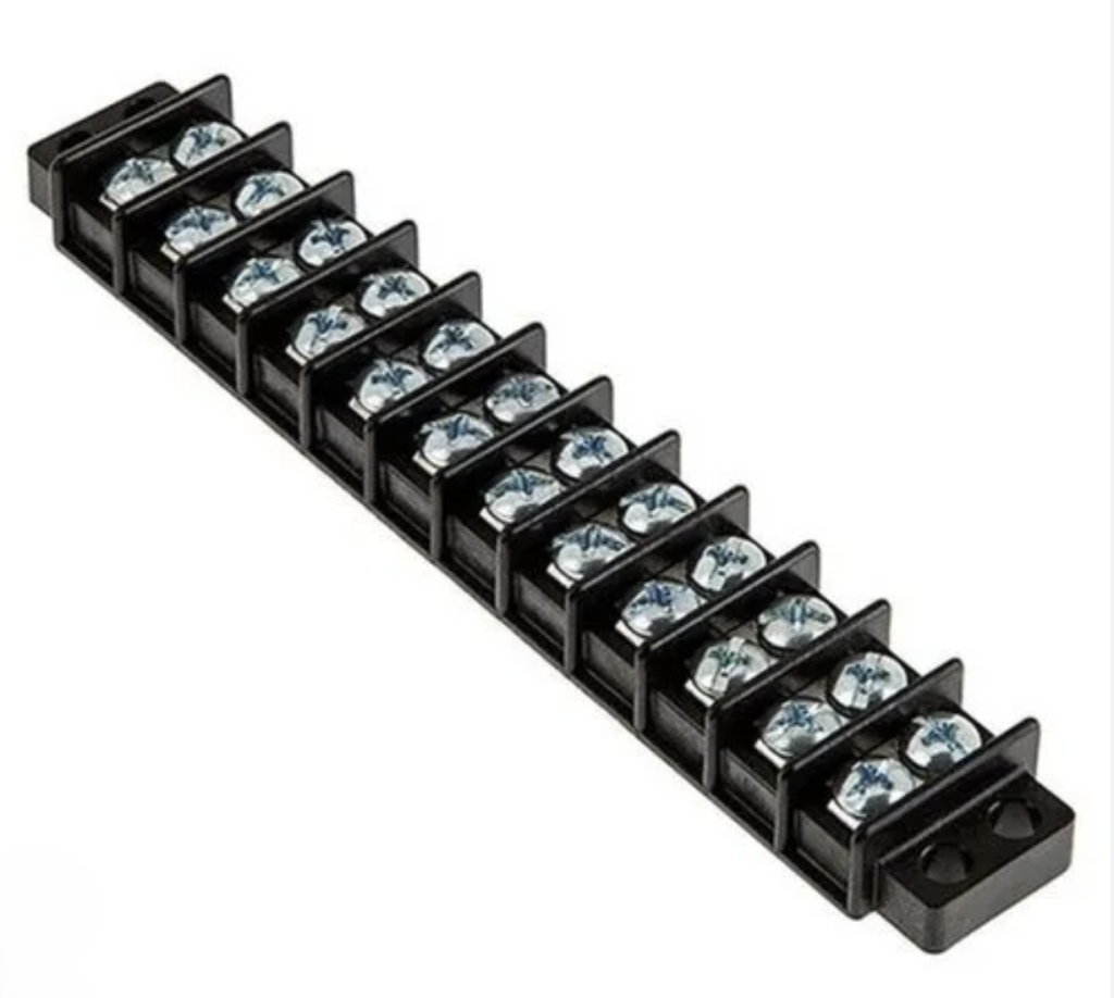
Designed for high-vibration environments, these have multiple connections in a single, flat row with rigid, insulating barriers between individual circuits to prevent arcing or shorts. Barrier strips hold each wire securely in place with a screw through a spade or ring terminal on each wire end. The highly insulated connections make this terminal block ideal for high-voltage applications.
Wire Clamping Types Within Terminal Block Housing
The wire clamp in a terminal block securely holds each inserted wire. The different designs account for wire size and type, vibration and other forces that may loosen connections, and ease of connecting/disconnecting input/output devices.
Screw Clamps (Yoke and Wire Protector Style)
Screw clips are among the more common wire clamping mechanisms in a terminal block. With these, the exposed wire end is held in place with a thin metal strip or collar that compresses it by turning a screw.
This clip is most often used with stranded wire. Proper installation ensures a secure connection.
Spring-Cage and Push-In Terminals
Ideal for solid wire, push-in clamps secure the wire with spring compression rather than a screw, much like a clothespin. The clamp pries open to receive the wire end with the pressure of the inserted wire. Since the spring tension can degrade with corrosion, connections should be protected from the elements and checked periodically. However, they are easier to use than screw clips.
Push-Button Actuated Contacts
These operate like push-in clamps, but the spring clamp opens with the push of a button at the top of the housing and secures the connection by releasing the button. Therefore, these can be used with stranded wire.
Internal Circuit Layout and Connection Architectures
These structures determine the number of circuits within each block and whether they are point to point or point to multi-point.
Single-level Pass-through
As the name implies, these terminal blocks have only one circuit connection. They connect one input wire to one output wire.
Dual-level Pass-through
Designed to save space, these terminal blocks have two separate circuit connections, one stacked upon another.
Multi-level Pass-through
As the name implies, these devices connect multiple, independent circuits within one housing. Tacuna Systems has two such options in its catalog, a 6-pin PCB terminal block and a 9-pin PCB terminal block.
Ground Terminal Blocks
Ground terminal blocks are similar in structure to single pass-through blocks, but the internal clamps connect the wires to an electrical ground.
Fused Terminal Blocks
Fused terminal blocks replace the metal connection between input and output terminals with a fuse for overcurrent protection.
Power Distribution Terminal Blocks
Unlike most terminal blocks, power distribution terminal blocks have one large gauge input connection point and multiple, smaller gauge outputs.
Important Terminal Block Specifications and Engineering Considerations
Beyond mounting configurations, clamp types and internal structures, the specifications below will help determine if a terminal block is right for your application.
Pole Count
Pole count refers to the number of individual circuits that pass through the terminal block. When thinking of pole count, consider whether the application will need future circuits, and plan for spare poles.
Pitch
Pitch is the physical space between circuits from clamp center to clamp center. It is usually measured in millimeters. The greater the pitch, the greater the protection from arcing.
Common pitch values are 2.54 mm (0.1″), 3.5 mm, 3.81 mm, 5.0 mm, and 5.08 mm (0.2″). Smaller pitches save board space but, again, reduce voltage isolation.
Wire Size and Type
As mentioned earlier, some wire clamps are best suited for stranded wire while others best accommodate solid wire. The clearance within the clamps influences the wire gauge that the terminal block can accommodate, along with its voltage and amperage ratings.
Engineering Note: How Terminal Blocks Compare to Other Wire Connection Methods
Terminal blocks aren’t the only way to join two wire ends. Twisting wires together and covering the joint with electrical tape or a wire nut is faster and cheaper for a one-off connection, but it offers no easy way to inspect, replace, or reroute the circuit later. Soldering creates a permanent, low-resistance joint, but like twisted connections, it cannot be undone without cutting the wire or breaking the solder joint, and it requires tools and skill to execute reliably.
Terminal blocks trade some of that simplicity for organization and serviceability. Because each connection point is a discrete, labeled, and mechanically secured slot, a faulty wire or device can be disconnected and replaced without disturbing any other circuit on the panel. This also makes terminal blocks the preferred choice in any application where wiring will be inspected, modified, or expanded over the life of the equipment. These include control panels, junction boxes, and machine wiring being common examples.
The tradeoff is space and cost. A terminal block’s housing, clamps, and mounting hardware add bulk and expense nonexistent in a twisted joint or solder connection. For permanent, low-maintenance connections where panel space is tight, soldering or crimped splices may still be the better choice.
Amperage Rating
Like all conductors, the terminal block’s amperage rating is based on its terminals’ conductivity, cross-sectional area, and heat generation. Generally, the terminal block should have an amperage rating of 150% of the highest current expected.
Note: Terminal block manufacturers typically publish derating curves showing how amperage capacity drops at elevated ambient temperatures. Always check the derating curve, not just the nominal rating.
Voltage Rating
A terminal block’s voltage rating depends on the housing’s dielectric strength and the pitch. This rating should exceed the circuit’s maximum voltage plus any possible surges.
Mechanical Structure
Mechanical structure refers to the orientation of the terminal block’s inputs relative to the outputs. The most common orientations are linear, 90 degrees, or 45 degrees.
Safety/Flammability Rating
Terminal block specifications generally give a safety or flammability rating. In North America, the UL 1059 standard governs these ratings, whereas globally, the IEC 60947-7 series of standards establishes safety ratings. A terminal block’s ratings should always exceed the most extreme conditions that a circuit may encounter in service.
Tacuna Systems Terminal Blocks
As mentioned earlier, Tacuna Systems offers two PCB terminal blocks, a 6– and a 9-pole version. They eliminate the need for hard soldering in circuits that use our EMBSGB200 embedded amplifier. (Specifications for this amplifier can be found on the product pages.)