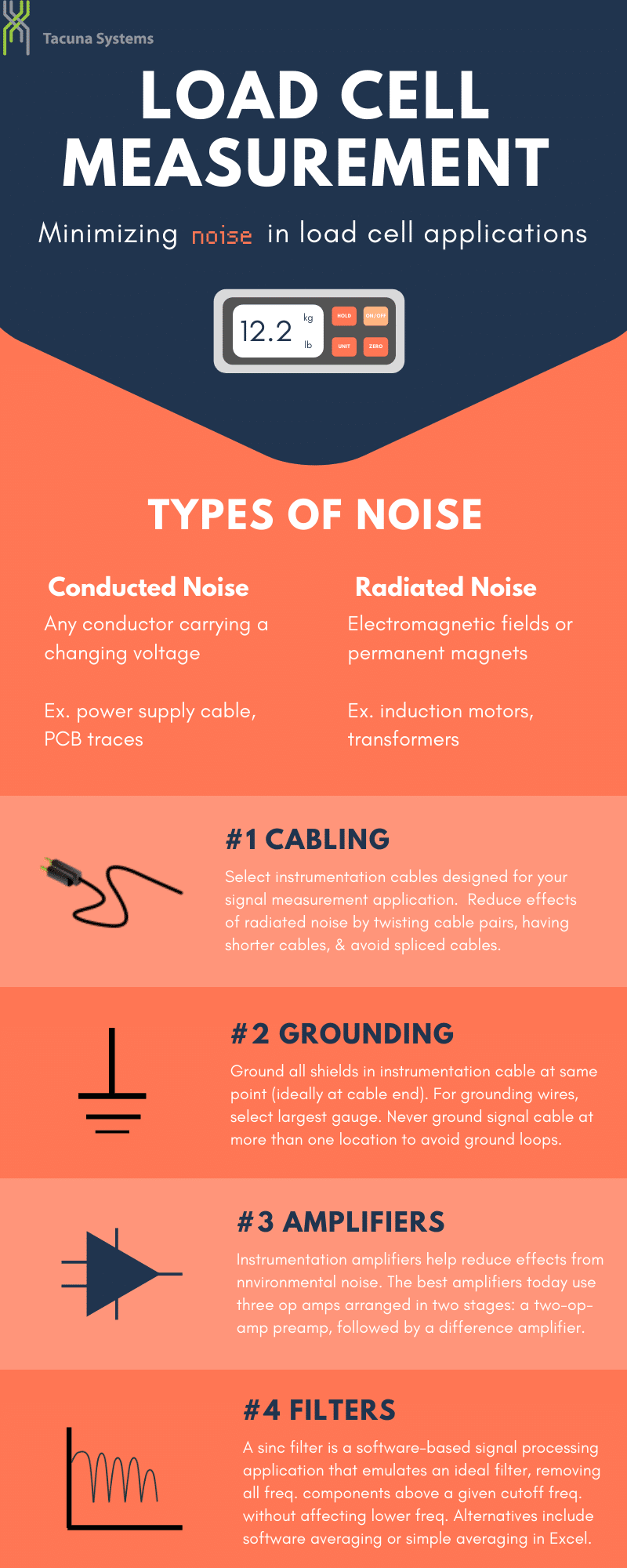
Load cells produce very small differential voltages, on the order of millivolts, when measuring a force. Consequently, these signals are easily degraded by unwanted voltages in the load cell output, such as those induced by environmental interference. When making very sensitive load cell measurements, it is imperative to mitigate this environmental noise to improve measurement accuracy. This guide gives field-tested best practices for electrostatic and electromagnetic noise reduction in load cell output signals.
Key Takeaways
- Load cell noise occurs with environmental factors such as power lines or vibrations. Since noise degrades the measurement signal, engineers need to employ techniques to reduce it.
- Best practices for minimizing load cell noise include the use of clean excitation sources, interference-resistant cabling, proper grounding, and the use of precision instrumentation amplifiers.
- Symmetrical full-bridge load cell configurations natively optimize common-mode rejection and maximize the overall signal-to-noise ratio (SNR) directly at the sensor.
- Digital sinc filters defend against industrial environments by dropping rejection notches at power line frequencies and their harmonics.
- Physical modifications, such as covering strain gauges and exposed lead wires with conductive metal foils, shield the circuit from external radiated noise paths.
Sources of Noise
To eliminate noise from a measuring system, it helps to understand how the unwanted energy enters the signal path. Generally, this occurs in two ways, categorized by how the noise travels: conduction (through hard wiring or physical connections) and radiation (airway frequencies).
Conducted Noise
Conducted noise enters the measurement loop through physical, conductive paths shared with or running adjacent to noisy equipment. This includes:
- Capacitive (Electrostatic) Coupling: Occurs when a wire carrying a changing voltage runs alongside your signal wires or printed circuit board (PCB) traces. This close proximity creates an unintended “invisible bridge” (parasitic capacitance) that leaks electrostatic noise directly into your signal path.
- Ground Loop Differentials (The 50/60 Hz Hum): Occurs when multiple pieces of equipment are grounded at different physical locations. These different ground points can have slight variances in electrical potential. This, in turn, forces an unwanted current to flow through your signal path. In industrial settings, this creates a persistent 50 Hz or 60 Hz AC hum that corrupts data.
Radiated Noise
Radiated noise does not require a physical wire connection. Instead, it travels through space via electromagnetic fields, using signaling cables as receiving antennas.
- Inductive Coupling (Near-Field): This happens when equipment like electric motors or transformers generate localized alternating magnetic fields. These fields pass through the air and induce an unwanted current directly inside nearby signal loops.
- Electromagnetic Radiation (Far-Field): This high-frequency noise travels widely through the air from everyday sources like WiFi routers, cellular networks, and fluorescent light ballasts.
Best Practices for Minimizing Noise in Load Cell Applications
An experienced weighing system designer uses these best practices to improve measurement accuracy.
Choose a Load Cell With a Full Bridge Configuration
A full bridge topology is the optimal choice for noise-sensitive systems, and it is the standard for high-precision load cells. All four branches of the Wheatstone bridge in this setup have nearly identical strain gauges. This internal symmetry ensures that environmental factors such as temperature drift or coupled electrical fields affect all four arms equally. In turn, this gives the sensor itself the ability for common-mode rejection (CMR), maximizing signal-to-noise ratio (SNR).
If a full bridge is unavailable, the viable alternatives are (in order of effectiveness): (1) a 3/4 bridge, (2) a half bridge, and (3) a quarter bridge with a 3-wire setup.
Ensure Excitation Power Supply Quality
Load cells are ratiometric devices, meaning their millivolt output signal is directly proportional to their input excitation voltage. Any electrical noise, voltage ripple, or high-frequency drift present on the excitation line will, therefore, directly alter the sensor’s output data. Other noise-mitigation efforts in this guide cannot correct these errors.
To ensure a stable measurement, always power your instrumentation using a highly regulated, low-noise linear DC power supply. Avoid using standard switching power supplies for sensor excitation, as they naturally introduce high-frequency switching transients into the DC lines. This conducted power-rail pollution travels straight into the bridge circuit, bypassing external cable shields entirely. For heavy industrial installations, incorporating isolated power barrier modules or dedicated linear sensor-excitation regulators is necessary to filter these lines and prevent high-frequency supply noise from bleeding into the differential signal path.
Connect with Suitable Cabling
Beyond the load cell itself, the most important factor for noise elimination is the signaling cable. Always use high-quality instrumentation cabling specifically engineered for low-voltage signal transmission.
- Twisted-Pair Architecture: Cables need to deliver both the incoming excitation voltage and the outgoing millivolt signal, requiring two pairs of wires. Twisting each pair ensures that any environmental noise couples onto both conductors equally. This allows the downstream amplifier to eliminate it as common-mode noise. If only flat, untwisted wires are available, a hand drill can be used on a low-speed setting to manually twist the lines into a functional twisted pair.
- Shielding Configurations: For optimal noise rejection, select a cable where each twisted pair is wrapped in its own independent foil shield; this eliminates internal crosstalk between the excitation voltage lines and the ultra-sensitive signal lines. At a minimum, ensure the cable features an overall shield (foil or copper braid) surrounding both wire pairs to block external radiated noise from penetrating the circuit.
- Cable Geometry and Connections: Keep all cable runs as short as possible to minimize total cable capacitance and limit the sensor line’s exposure to ambient fields. Avoid using spliced cables whenever possible, as a splice junction breaks shielding continuity and creates an immediate entry point for noise. If a field splice is unavoidable, you must keep the shield and drain wire completely intact across the junction and secure the connections by soldering or using tight screw terminals or crimp connectors. The best option is to use a cable splicing kit since it protects the junction’s electrical integrity.
Use Proper Grounding Architecture
Behind cable choice, proper system grounding is imperative for noise elimination. In a sensitive load cell application, an effective grounding strategy accounts for both signal cables and AC power distributions.
- Single-Point Shield Grounding: Ground all of the shields in the instrumentation cable at the exact same point, ideally at the instrumentation or data acquisition end of the cable. Never ground a signal cable shield at more than one location. Grounding a shield at multiple points creates a closed loop that intercepts stray magnetic fields. This will generate a ground loop current that introduces severe electrical noise directly into the signal path. If you must use dedicated grounding wires, use the largest wire gauge and shortest length possible to minimize resistance.
- Terminating Unused Conductors: If you have unused conductors inside a signal cable, do not leave them disconnected or floating. Doing so will essentially make them antennas that absorb ambient environmental interference. Always tie these unused signal conductors to your established single-point system ground, along with their surrounding shield.
- Common Power Referencing: Plug all interconnected signal-handling equipment into a single power strip if possible. This forces all devices to use a common ground reference point, preventing AC ground differentials (such as the 50 Hz or 60 Hz hum mentioned earlier) from corrupting the measurement loop.
Use Instrumentation Amplifiers
All low-voltage load cell measurements require the use of an instrumentation amplifier to scale the sensor’s tiny output signal. The most effective instrumentation amplifiers today feature a three-operational-amplifier (op-amp) architecture arranged in two discrete stages: a two-op-amp preamplifier stage followed by a difference amplifier.
Beyond scaling the signal, these devices are a critical component in reducing the effects of environmental noise. They do so through common-mode rejection, ignoring the identical voltages (while amplifying the differential ones) on the two load cell signal wires. These signal wires share the noise energy equally due to their proximity.
Filter Common Unwanted Frequencies
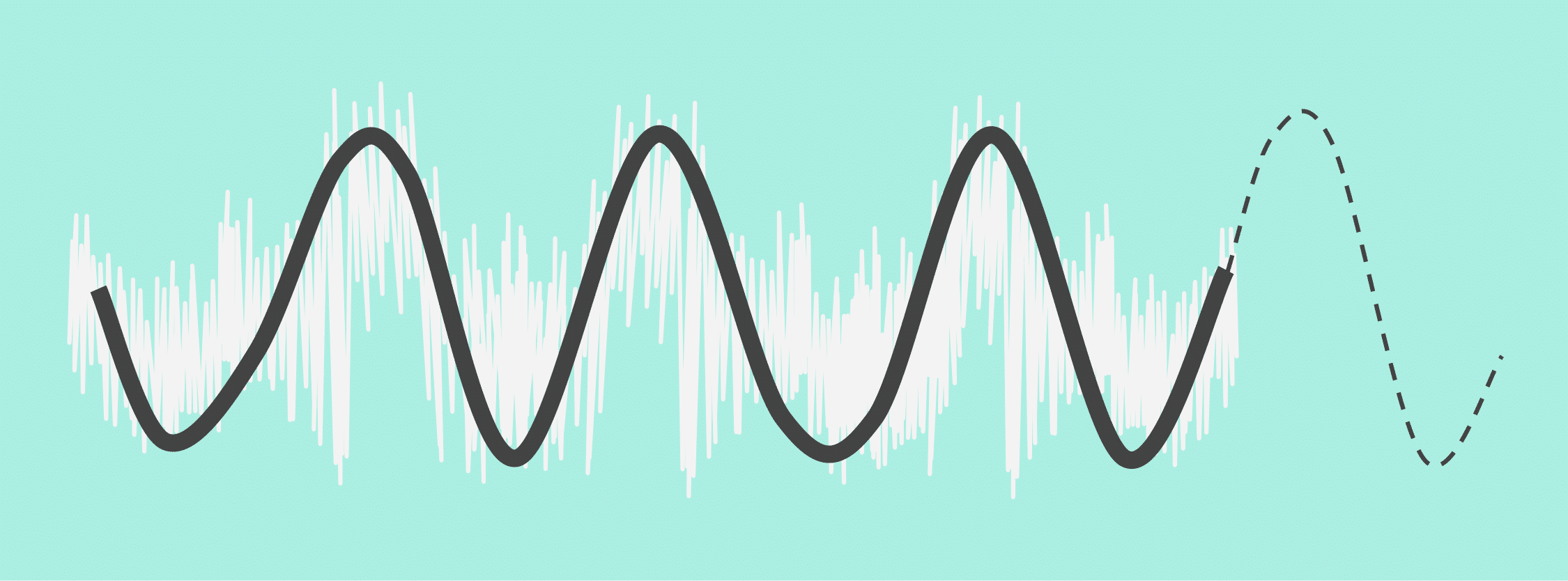
The optimal filter to eliminate other noise components is a software-based digital signal processing application known as a sinc filter. This filter emulates a mathematically-ideal one by removing all frequency components above a specified cutoff frequency without affecting any of the lower, primary measurement frequencies.
Crucially, a sinc filter also acts as a notch filter, rejecting 50 Hz or 60 Hz frequencies and all their harmonics (integer multiples). This mathematical precision allows it to completely wipe out persistent industrial power line hum and the harmonic distortion caused by surrounding machinery.
Additionally, a sinc filter helps mitigate thermal noise. Thermal noise is intrinsic to the electronic components themselves, making it completely unsolvable by physical shielding or grounding. This means bandwidth-limiting digital filters are the primary line of defense against it.
Because this is an advanced, algorithm-driven filter, it is typically not a straightforward DIY project to program from scratch. However, accessible software alternatives can achieve basic signal smoothing, such as software-based moving averages or simple data averaging within Excel.
Implement Physical Shielding and Environmental Isolation
Beyond internal circuitry and cabling, physical modifications to the sensor’s immediate environment provide a final layer of defense against intractable radiated noise. To shield them from radiated noise, a best practice is to physically cover strain gauges and their exposed lead wires with aluminum or tin-plated copper foil. These foil shields must be grounded in the exact location as the signal cable shields. To prevent accidental short circuits, always coat the underlying solder joints in a dielectric sealant or insulate them with rubber, Teflon, or Kapton tape before applying the conductive foil wrap.
Component isolation is equally critical to maintaining signal integrity. There should always be a maximum physical distance between any sensitive measurement circuit and high-power or radiating equipment. Common workshop items like fluorescent light fixtures, WiFi routers, and even hot soldering irons can corrupt signals and, therefore, should be as far away from the measuring area as possible.
Finally, keep in mind that standard copper or aluminum foil shields are only effective against electrostatic fields. They are transparent to magnetic fields such as those generated by massive electric motors or transformers. In these situations, encase the vulnerable components in specialized, high-permeability alloys like Mu-Metal®.
Conclusion
Noise is present in most, if not all, environments where load cells operate, and it affects their measurement accuracy. This guide introduces ways to minimize its impact through proper excitation, cabling, grounding, and shielding techniques. Furthermore, signal conditioners such as amplifiers electronically “clean” output signals.
If signals remain unstable or noisy in spite of using all these techniques, the load cell itself may be faulty and require replacement.
For more information on these topics, refer to the following documents in Tacuna Systems’ Knowledge Base: