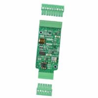
TBX Wireless Load Cell Bridge
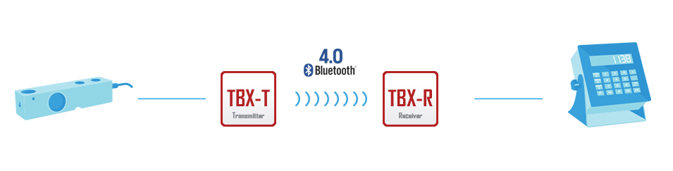
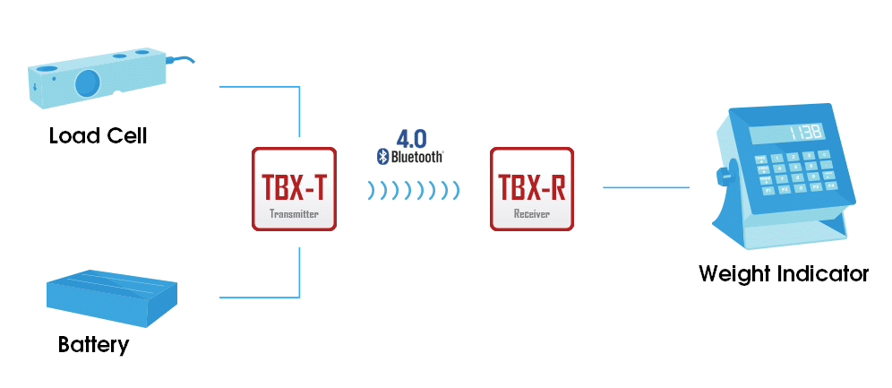
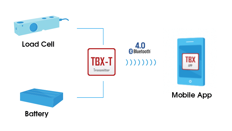
Turn any standard analog load cell into a wireless load cell with a TBX Wireless Load Cell Bridge. This system replaces the physical cable connection between the load cell and the weight indicator. The TBX Wireless Load Cell Bridge can be retrofitted into old systems or designed for new systems.
| Quantity | Price |
|---|---|
| 1 - 9 | $499.95 |
| 10 - 24 | $474.95 |
| 25 - 49 | $459.95 |
| 50 - 99 | $444.96 |
| 100 + | $424.96 |
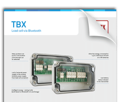
TBX Wireless Load Cell Bridge Features
- Ultra-low energy consumption
- Clamp connectors (vibration resistant)
- Additional LED module indicating system status
- Low battery status indicator (via RS 232 port and LED)
- Energy saving mode (sleep mode activates in the absence of a change in mass value)
- Receiver powered directly from load cell connector (no external power supply)
- Multiple-system operation in one location (up to 128 channels)
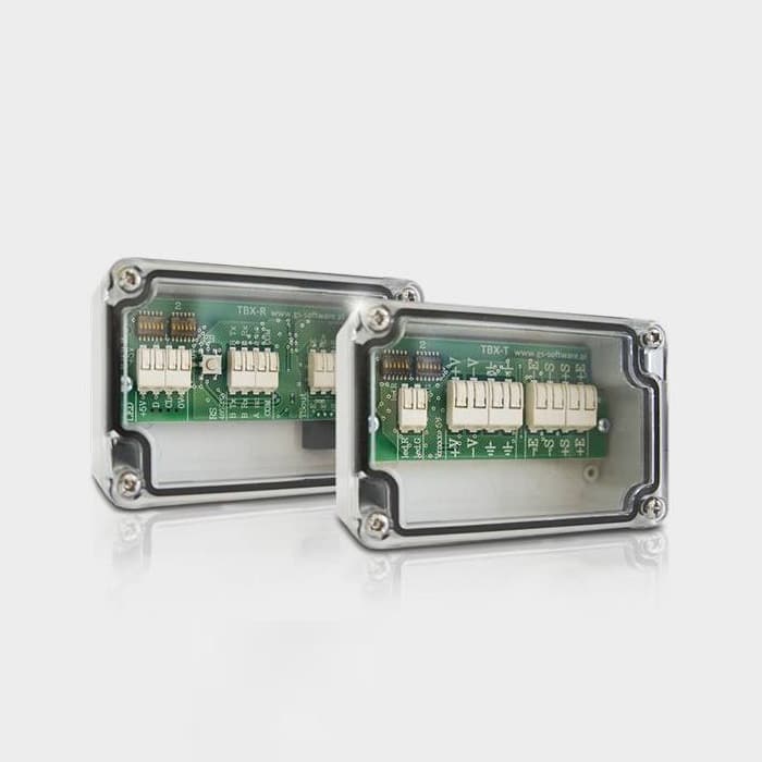
Available options: TBX Pair (R&T), TBX-R, TBX-T
Please contact us with any product-related questions.
Tacuna Systems Commitment
We strive to help our diverse customer base achieve their desired outcomes. As a small business, we take great pride in providing free consultation for product design & prototyping to ensure our valued clients have the right equipment to be successful. Our engineering specialists have extensive R&D experience in strain gauge load cell technology, and we are well-known for our in-house designed customizable signal conditioners and amplifiers.
Specifications
TBX-R (Receiver)
| Receiver | Connected to the weight indicator as a load cell |
| Power supply voltage from the weight indicator | 5 – 10 VDC |
| Power consumption | max. 25mA |
| Constant emulated load cell | 2.0 mV/V |
| Emulated voltage | Proportional to the voltage come from the indicator |
| D / A converter | 16-bit, effective resolution 16-bit |
| Zero drift of amplifiers | <5ppm/K |
| Resistors in the analog circuit | 0.1%, 25ppm/K |
| Total error after calibration (estimated) | max. 90ppm/K (0.009%/K) |
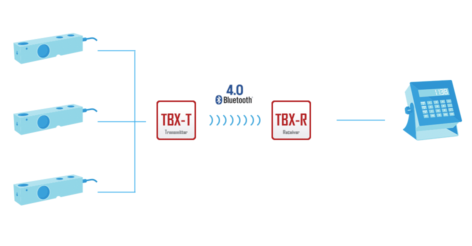
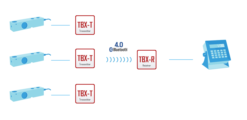
| Number of transmitter connected to one receiver | 1 – 4 |
| Number of channels | 1 – 128 |
| Port RS 232 (RX, TX, COM) | For signalling the battery status in the transmitter |
| Configuration button | To set the signal level in case of no connection with the transmitter |
| Working temperature | From -40˚C to 85˚C |
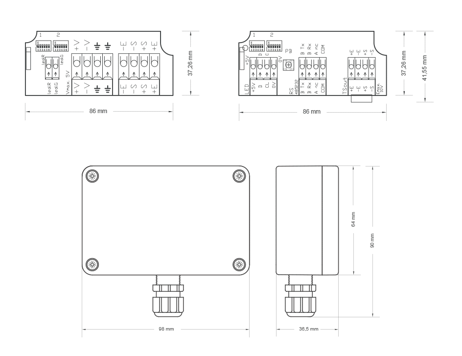
| Dimensions | 86x47x12 mm (without housing) |
TBX-T (Transmitter)
| Load Cell Excitation | ~2,8 VDC max 100mA |
| D / A converter | 16-bit, effective resolution 16-bit |
| Frequency of measurement | 4.17x/sec (max. 50x/sec) |
| Resistors in the analog circuit | 0.1%, 25ppm/K |
| Total error after calibration (estimated) | max. 75ppm/K (0.0075%/K) |
| Power | 3.7 ~ 5 VDC (ie. 3 x AA battery, Li-Ion / Li-Po 3.7V) |
| Power consumption without load cell | < 5mA |
| Power consumption by a 360Ω load cell | 9.2 mA |
| Power consumption in sleep mode | < 0.3mA |
| Type of antenna | Integrated |
| Working temperature (without battery) | From -40˚C to 85˚C |
| Dimensions | 86x37x9 mm (without housing) |
Additional Information
| Radio | Bluetooth 4.0 Low Energy 2.4 GHz |
| Working distance | 20 meters |
| Connectors | Clamp – vibration resistance |
| Tool for mounting connectors | WAGO 206-861 |
| Compliance with the directives | CE, RED, RoHS, MD |
Technical Diagrams
Working Modes
Load Cell Configuration Types