
Build a digital scale for your next Do-It-Yourself electronics project. Whether you’re looking to increase your background learning around force measurement or in search of a school science project, this DIY electronics project can be completed by anyone with a basic understanding of electronics and computer programming.
The components used to build the digital scale in this article can be found in the Tacuna Systems shop.
What is a Digital Weighing Scale?
Digital weighing scales are common in our everyday lives, from the produce section grocery stores to our own bathrooms.
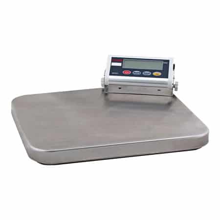
A digital scale is an electronically operated device that displays the weight/size of an object placed on it in numbers and units. This display is usually liquid crystal or 7-segment display.
Scale Components and Function
Now that we have established what a digital scale is, this section lists and describes its fundamental internal components.
Load Cell Transducer
This device senses an applied weight and produces an observable output electrical signal proportional to this applied weight. There are different types of load cells and not all load cell sensors are transducers, but all load cell transducers are sensors. To clarify, a sensor is a device that detects a physical phenomenon such as a force and then produces a change in a physical parameter. In the same way, the transducer senses this physical phenomenon but converts it to an electrical output signal.
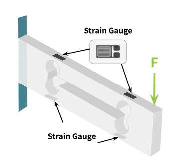
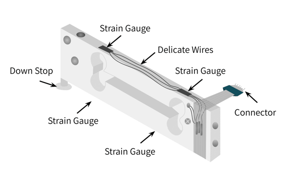
Examples of load cells are the pneumatic load cell, hydraulic load cell, strain gauge load cell, or capacitive load cell (See An Overview of Load Cells for more information). The most common type used in digital scales is the strain gauge load cell. The strain gauge load cell is a transducer device that has an underlying mechanism called a strain gauge. The strain gauge has a resistive and elastic metal foil material that is fixed and attached to the bending parts of the load cell as shown in the figures below.
The Signal Conditioner
This is a circuit device that has two functions. It amplifies load cell output voltage and filters both its input and output signals. Since the output of the load cell is always very small, measured in mV, this device is critical to amplify the load cell output to a usable level. Load cell signal processing requires a special type of amplifier called the instrumentation amplifier. The filter circuit can be embedded together with the amplifier on a single chip. This circuit filters noise signals and electromagnetic interference (EMI) that might compromise the load cell’s amplified signal. It decouples AC signals from the DC output signals. Tacuna Systems offers a signal conditioning device described at this link.
The Microcontroller
This is the central processing unit of the whole digital scale. The analog output of the signal conditioner flows to the analog input port of the microcontroller, which in turn converts this analog signal to digital. Note that some signal conditioners have an analog to digital converter circuit together with the amplifier circuit and the filter circuits on a single chip. This reduces the workload on the microcontroller, as the output of the signal conditioner instead goes to the digital input port of the microcontroller. The microcontroller then reads the clocked digital pulses from the conditioner to obtain the data it processes to determine the weight displayed. Finally, the microcontroller computes the weight and then displays it through its connected LCD screen.
The Liquid Crystal Display
As explained above, this is the screen that connects to the microcontroller to display the weight.
Coupling These Components
To build a digital scale yourself, we will use the following components coupled together:
- A 5kg load cell
- An HX711 amplifier
- An Arduino Uno Microcontroller Unit (MCU)
- Any suitable output screen (in this case an Arduino IDE Serial Monitor)
The physical process to connect these components is outlined in the next two sections.
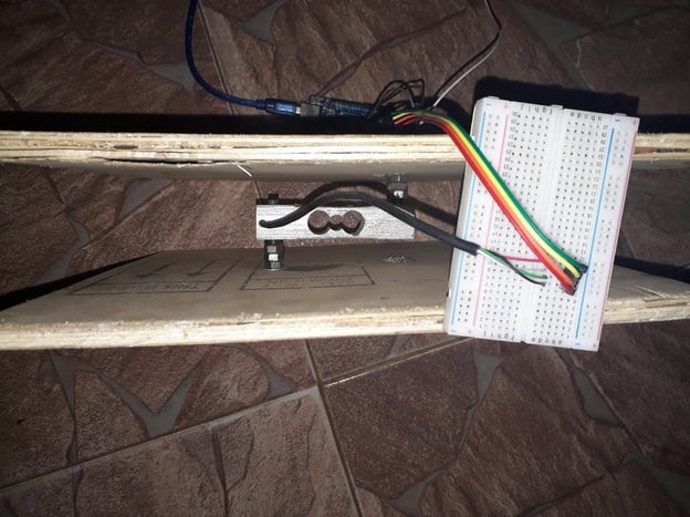
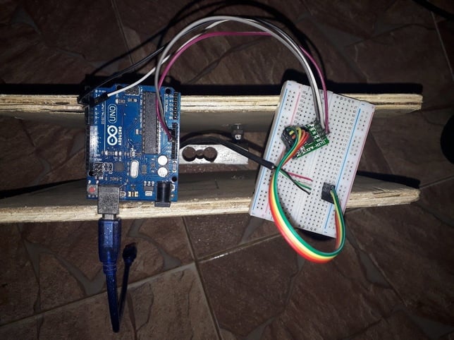
Note that in Figure 4, the scale is turned on its side to show the connections. Notice there are two wooden boards connected to alternate ends of a single point load cell. One board forms the base and the other the loading platform. Any convenient flat, sturdy material can form these two components.
The Hardware Setup
The 5kg load cell for this project has four wires (some load cells have 6). The wires are as follows, according to the load cell’s datasheet.
- Red wire is the positive power supply
- White wire is the Ground of the power supply
- Black wire is the positive output
- Green wire is the negative output
Any extra wire, which might be any color such as blue or yellow, is the ground wire for EMI. It should be connected to the power supply ground.
Note the wiring diagram depends on the datasheet of the purchased load cell. Therefore the colors listed above could match differently (such as green being positive, etc.). Be sure to always request a datasheet from your supplier with your purchase.
Load Cell to Amplifier Connection
The wires listed above attach to the appropriate pins of the HX711 amplifier device as shown in the sets of pictures below. The HX711 is a special amplifier that has 2 channel inputs A and B, each with different amplifier gains adjustable by a computer program. The channel A has a gain of 128 and 64, while the channel B has a fixed gain of 32.
Note this HX711 device matches the description of the type of signal conditioning device that has an amplifier, filter, and analog-to-digital converter (ADC) embedded together on a single chip. This means its data output goes to the digital input pin of our microcontroller instead of its analog pin.
Therefore, connecting the HX711 and the load cell is as followed:
- Red wire/Positive supply -> E+
- White/Negative Supply -> E-
- Green/Negative Ouput -> A-
- Black/Positive Output -> A+
Amplifier to Microcontroller Connection
After connecting the amplifier, the next step to build the digital scale is to connect the microcontroller. The HX711 connects to the Arduino MCU as follows:
- VCC -> 5V supply on Ardunio
- GND ->GND
- CLK -> D2
- DOUT -> D3
The Code
Once the hardware connections are complete, the next step to build the digital scale is to upload the program code to the MCU from a PC through the Arduino IDE. The process and the code have two subdivisions: the calibration code and the weighing code.
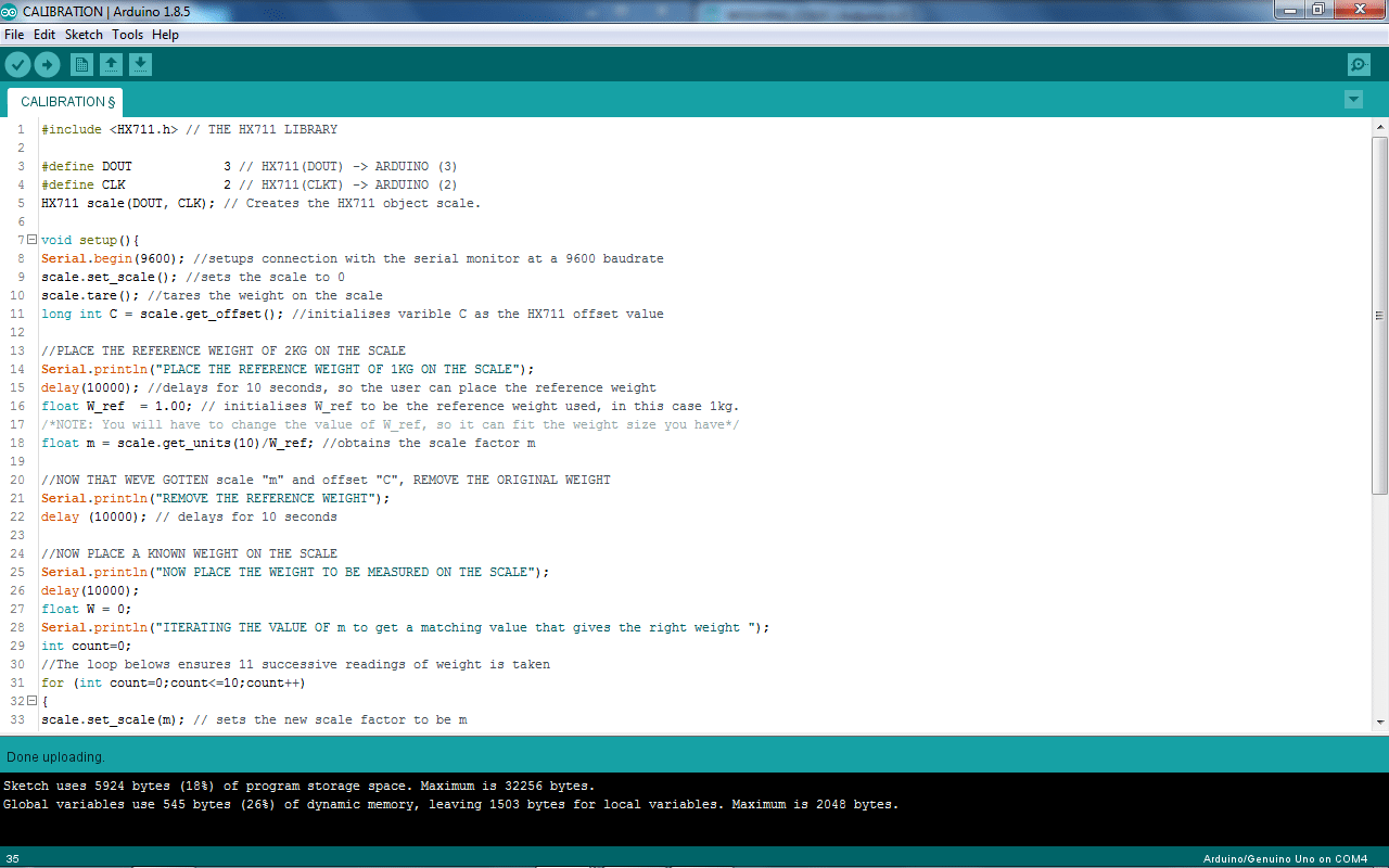
Calibration Code
The calibration code is the program used to calibrate the load cell transducer. Calibration configures the load cell output to always give a precise value of weight and at the particular SI unit such as Kilograms, Grams, Tons, Pounds etc.
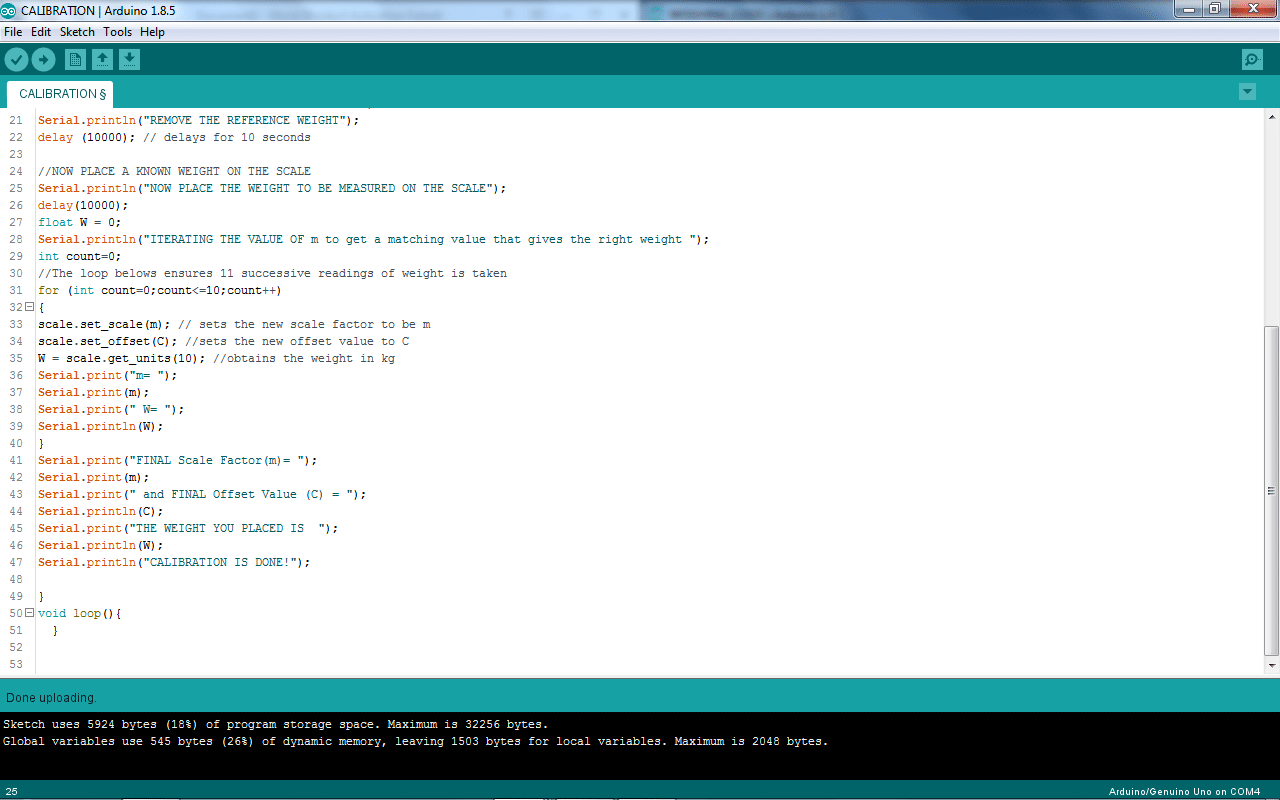
The HX711 library code contains a good guide on how to calibrate the load cell. The calibration code is shown in Figure 6a-b.
The results of the calibration process are shown below in the Serial Monitor of the Arduino IDE.
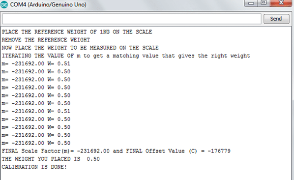
Note in Figure 7 the “FINAL Scale Factor” and the “FINAL Offset Value”. These values are critical to obtain before uploading the weighing code.
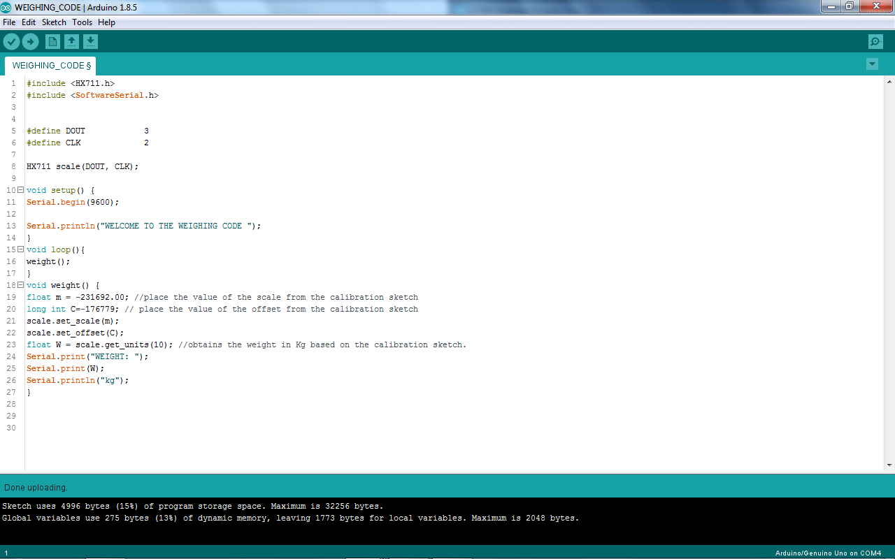
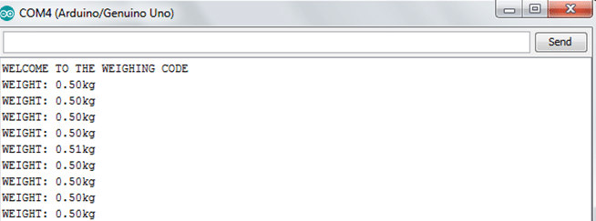
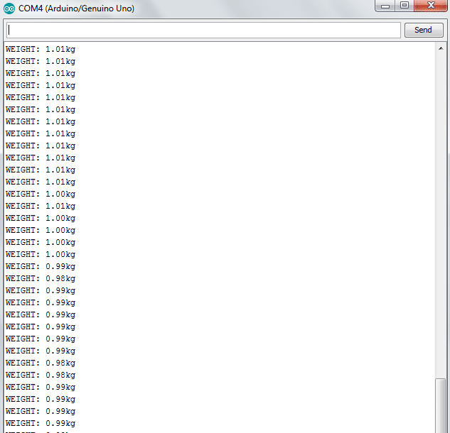
Weighing Code
Once calibration is complete, the weighing code uploads to the MCU. This code appears in Figure 8 below. The figures that immediately follow, Figures 9a-b, show the readouts for a 500g weight (top) and a 1kg weight (bottom).
And with that, the process of building the digital scale is complete!
Conclusion
This article has presented one way to build a digital scale. It also provides some insight into how these scales work. The components are easily obtained from our shop; however, Tacuna Systems also offers a full range of scales below, for those not inclined to build your own digital scale.