
In the article, The Versatile Strain Gauge Load Cell, we explain the internal bridge circuitry of this measuring device. This basic Wheatstone bridge circuit is a four-wire system. However, four-wire load cells are not suitable for every application. Systems that require long cable runs or experience wide temperature swings, among other reasons, benefit from compensation circuitry. One such compensation method is to add a pair of sense wires. They compensate for changes in resistance, giving system designers more flexibility in swapping out cabling or the load cells themselves without impacting system calibration.
This guide compares a four-wire strain gauge load cell to a six-wire one at the circuit level and weighs the options for when each is suitable.
Key Takeaways
- Load Cell Cabling Alternatives: A four-wire load cell uses two wires for power and two for signal output, while a six-wire configuration adds sense wires for voltage compensation.
- Cable Length and Calibration: Factory calibration is tied to the original cable length provided with the load cell. Cutting, shortening, or significantly extending this cable alters the resistance, which induces measurement errors in 4-wire systems.
- The 6-Wire Solution (Sense Leads): Unlike 4-wire cables, 6-wire configurations use “sense” leads that provide feedback to the indicator/amplifier. This allows the excitation source to compensate for voltage drops in the cable, maintaining measurement accuracy regardless of distance or temperature-induced resistance changes.
- Grounding and Shielding: The shield wire is not part of the measurement bridge and should never be used as a ground for the indicator. To protect against EMI/RFI, the shield should connect at the indicator end only (the “single-point ground”) to prevent ground loops.
- The “Jumper” Necessity: When using a 6-wire load cell with a 4-wire indicator (or vice-versa), you must correctly jumper the excitation and sense terminals. Failure to complete this circuit will result in an “Open Sense” fault or an unresponsive system.
- Tacuna Systems offers both types of load cells to meet our customers’ needs.
The Four-Wire Load Cell
In the four-wire system, two wires supply power to the Wheatstone bridge: the positive and negative input terminals. The other two wires are the signal output terminals of the bridge, likewise positive and negative. Figure 1 shows this wiring system, typically found in a bending beam load cell.
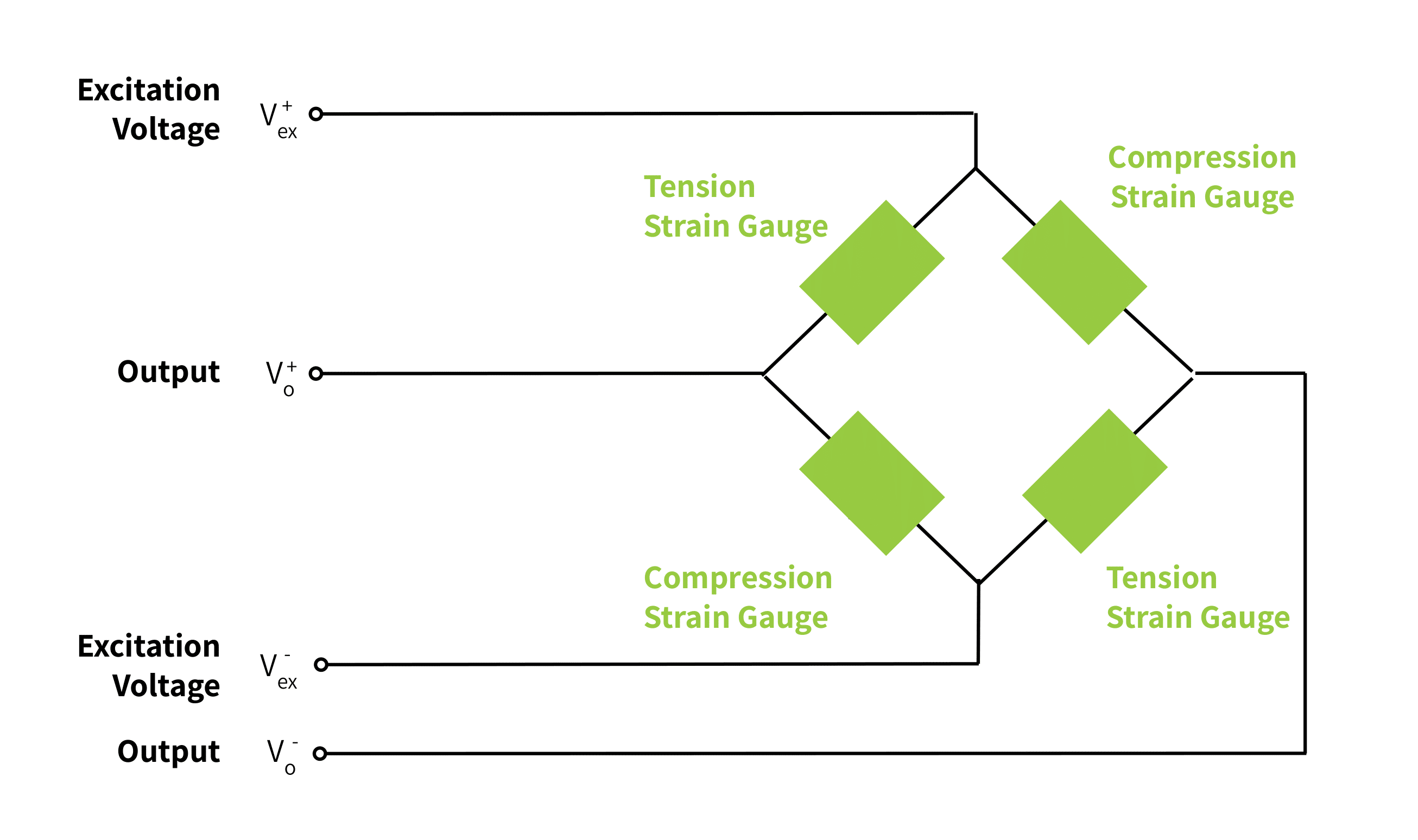
Most textbooks and articles show the lumped parameter model of the strain gauge Wheatstone bridge and its connections. The lumped parameter model ideally assumes that the connecting wires to and from the Wheatstone bridge have zero resistance.
However in practice, there is a detectable voltage drop over the wires themselves. This is not a problem as long as the length of wire at both the inputs and outputs remains unchanged throughout the usable life of the load cell. All of the load cells in Tacuna Systems’s online catalog are precalibrated with this known length of wire; therefore their wire resistance is accounted for in the performance characteristics listed on their specification sheets.
As a few of our FAQ questions point out, cutting cables alters the calibration of a four-wire load cell. However, inserting a cable connector in the same-length cable run will not measurably alter a load cell’s calibration (provided it is a quality, corrosion-free connector designed for this purpose). This setup makes it more practical to replace the load cell in a measuring system if necessary.
In applications where it may not be practical to keep extra lengths of wire, or in ones with long cable runs, a six-wire load cell may be more desirable. Likewise, applications that experience wide temperature variations may require sense wire-equipped load cells. Since cable resistance affects the calibration, any temperature-induced resistance change in it will introduce a small span error that the four-wire configuration cannot self-correct.
The Six-Wire Load Cell
In practice, a distributed parameter model is more accurate than the lumped parameter model of the bridge circuit. This model assumes connecting wires actually have resistance to the flow of current. This means the wires’ length, cross-sectional area, and resistance variation with temperature influence the bridge’s design.
A six-wire strain gauge load cell accounts for the effects of these distributed parameters. It has the same power supply/excitation and signal output terminal wires as its four-wire counterpart. However it also has a positive and negative sense wire. The sense terminal wires connect at one end to the same nodes as the power supply wires. Figure 2 below illustrates this.
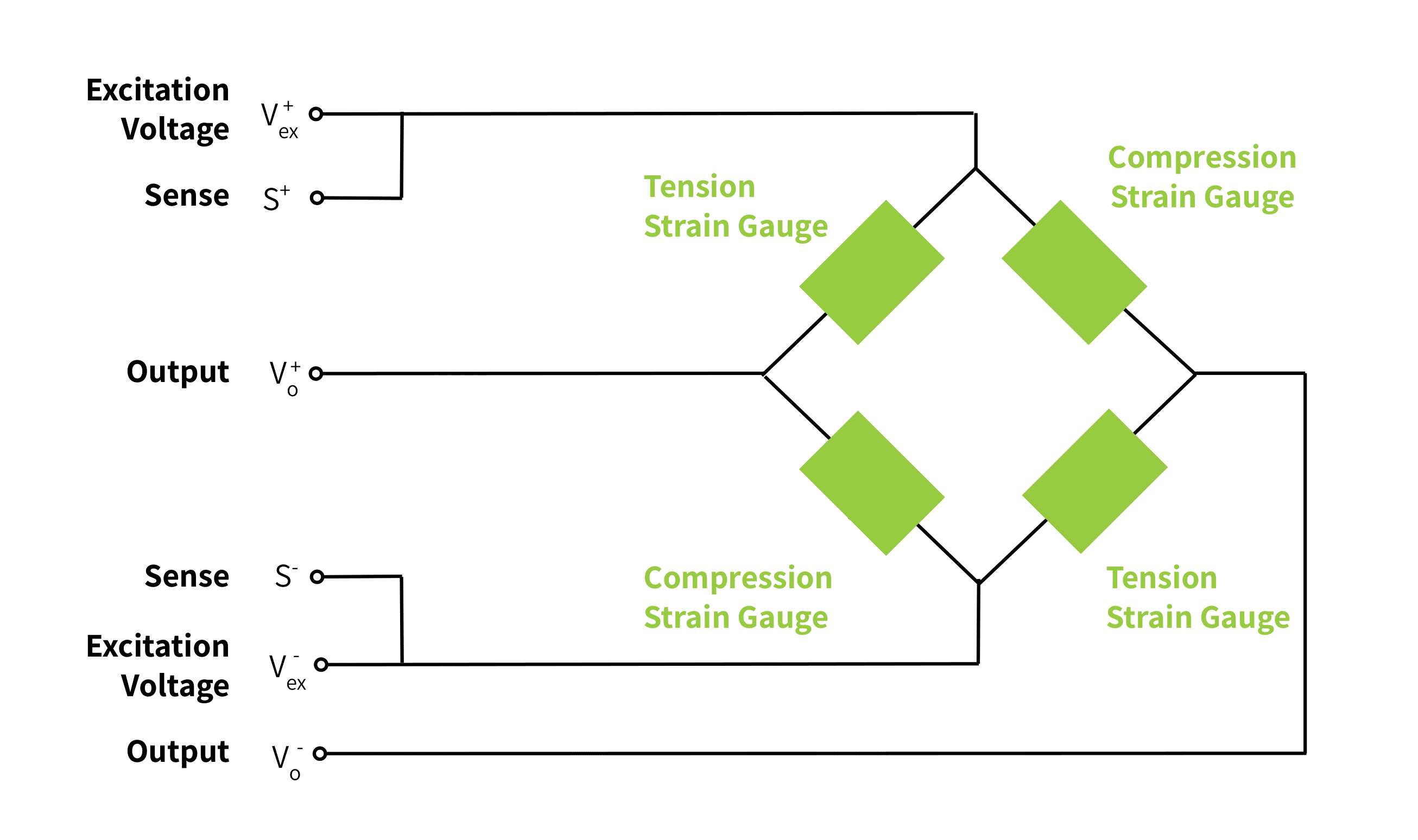
The other ends of the sense wires connect to the indicator’s (or amplifier’s) sense inputs. This device’s internal excitation regulator reads the voltage on these sense lines and adjusts its excitation output accordingly. This keeps the voltage that reaches the bridge constant, regardless of variable cable resistance.
Because the six-wire system integrates this simple voltage controller design with the Wheatstone bridge, it is the best choice for implementations where cable runs may vary or have exposure to temperature variations.
Other Strain Gauge Load Cell Wiring
An additional shield wire may be present in both the four- and six-wire strain gauge load cells. Depending on the manufacturer’s design, this shield wire may connect to the load cell body or remain floating at the load cell end. It is typically grounded at the indicator or instrument end to avoid ground loops. The shield wire is one way to protect the load cell’s internal circuitry from electromagnetic interference. Other methods, such as twisted pair wiring, are covered in our guide, How to Reduce Noise in Load Cell Output Signals.
The shield wire is not intended for use as, nor should it ever be wired to, a ground.
A Practical Example of the Six-Wire Connection
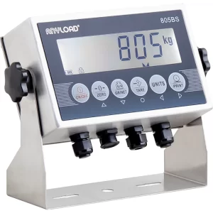
Most of the load cells in Tacuna Systems’ online catalog are available for special order with a six-wire configuration. The 805BS Load Cell Indicator is capable of either 4-wire or 6-wire configuration.
Pro-Tip: Using a 6-Wire Load Cell with 4-Wire Instrumentation
If your indicator terminal block has Sense+ and Sense- ports, but you are using a 4-wire load cell, you must “jump” the sense leads to the excitation leads at the indicator. Use a jumper wire to connect the Exc+ to the Sense+ terminal and the Exc- to the Sense- terminal. This ensures the indicator receives an excitation voltage reference, preventing it from reporting an “Open Sense” error or failing to power the bridge. Likewise, when connecting a 6-wire load cell to an indicator without sense wire inputs, jumper the positive and negative sense wires to their corresponding excitation leads at the terminal block or junction box before connecting to the excitation source.Note: While this ensures the system functions, the cable-resistance compensation benefits of a true 6-wire configuration are lost.
Diagnostic Testing of Sense Lines
Because sense lines are connected to the same points as the excitation leads inside the cell, a simple resistance check between them is one of the most useful field diagnostics available.
How to Perform the Test
- Disconnect the load cell connector from the indicator or junction box so you are measuring only the cell and its cable.
- Set a digital multimeter (DMM) to the ohms (Ω) range.
- Measure the resistance between Exc+ and Sense+.
- Measure the resistance between Exc− and Sense−.
Interpreting the Results
| Measurement | Reading | Diagnosis |
|---|---|---|
| Exc+ ↔ Sense+ | ≤ a few Ω | Healthy connection; sense and excitation leads joined at the bridge |
| Exc− ↔ Sense− | ≤ a few Ω | Healthy connection |
| Either pair | Open (∞) | Broken sense wire, cold solder joint, or disconnected terminal |
| Either pair | Tens of Ω or higher | High-resistance joint, corroded terminal, or damaged cable |
Note: For a healthy connection, the small resistance you do see is simply the round-trip conductor resistance of the sense wire itself (typically a few tenths of an ohm to ~2 Ω depending on cable length and gauge). If the reading is noticeably higher than expected for the wire run, investigate the cable and termination points for corrosion, nicks, or poor solder joints.
Why Perform a Sense Wire Check?
A faulty sense line does not always cause an outright failure. Instead, the indicator may revert to four-wire operation or display an unstable reading. Performing this quick ohms check at initial deployment or during routine maintenance catches problems before they corrupt weight data. A thorough field evaluation pairs this test with the standard excitation-resistance and signal-resistance checks (such as verifying that excitation resistance matches the load cell spec sheet within tolerance).
Tip: While you have the DMM connected, also verify that the resistance between each conductor and the cable shield exceeds 1 MΩ. Low shield-to-conductor resistance points to moisture ingress or insulation damage.
Conclusion
This article compares the four- and six-wire electrical connections of strain gauge load cells, and explains the additional shield wire. Note that the same sense wire compensating technique can be applied to other transducer types.
Design and implementation considerations beyond the scope of this article exist. These are discussed in more detail in the articles below.
Further Reading
- Load Cell FAQ
- The Versatile Strain Gauge Load Cell
- Choosing the Right Load Cell For Your Job
- Calibrating the Force Measuring System
- How to Reduce Noise in Load Cell Output Signals
- How to Test for Faults in Load Cells
- Why Do I Need a Load Cell Amplifier?
- Load Cell Summing: Junction Boxes, Signal Trim, and Excitation Trim
- …and other articles in the “Load Cell How To” section of our Knowledge Base.
References
- The Instrumentation Reference Book Edited by Walt Boyes
- Force Measurement Glossary by Tacuna Systems