
This article explains the techniques used to measure forces diverted from the desired force direction (a “force shunt”), to derive accurate force data. This measurement is important when other methods of compensating for diverted forces are impractical. It begins with the concepts of force sensors and transducers. It concludes with a brief overview of calibration of these devices.
Key Takeaways
- This article describes how to measure force shunts to compensate for them when other methods fail. This compensation is necessary to derive accurate force data.
- Direct force measurement captures the main process force, while force shunt measurement quantifies diverted forces.
- Strain gauges and strain gauge transducers are common methods for measuring force shunts, each with its own advantages and disadvantages.
- Calibration is crucial for accurate measurements in the presence of force shunts, ensuring reliable data from force transducers.
Force Sensors and Transducers
Force sensors are devices that respond to or detect physical force caused by a physical load, weight or pressure. A force transducer is a force sensor that converts this physical force into an output electrical signal (voltage or current). Examples include piezoelectric transducers, strain-gauge load cells, pneumatic and hydraulic pressure transducers.
Force transducers are often integrated into process control systems. An example is a filling system where measured weight tells the system the vessel is full and filling can stop. When these control systems are open-loop, calibration must occur to obtain accurate results (see the article, Calibrating the Force Measuring System, or a quick summary in the section below).
Accurate measurements depend not only on proper calibration, but also proper placement and orientation of the object applying the force. Force measurement techniques involve this interface between transducer and object or device generating the force.
Force Shunts
In electronics, a shunt is a device that creates a path of low resistance, diverting the flow of electric current through another point in the circuit. Simply put, the electric current will flow through the shunt because it has low resistance.
Similarly, a force shunt can be defined as a structure that diverts the main process force through a path of low force resistance. Examples include support devices such as check rods and chains. This article specifically considers the mechanical force created by their physical load, weight, or pressure.
A force shunt is different from an electrical shunt since the latter diverts most of the electricity through the shunt; with the former, less of the force typically diverts. However the underlying concept is the same. Measuring these forces becomes important for various reasons. Firstly we want to capture the amount of force diverted. Additionally, we want to ensure forces do not exceed a level where safety and support devices could fail.
Force Measurement
Two main ways to measure forces are direct force measurement and force shunt measurement. Their definitions are as follows:
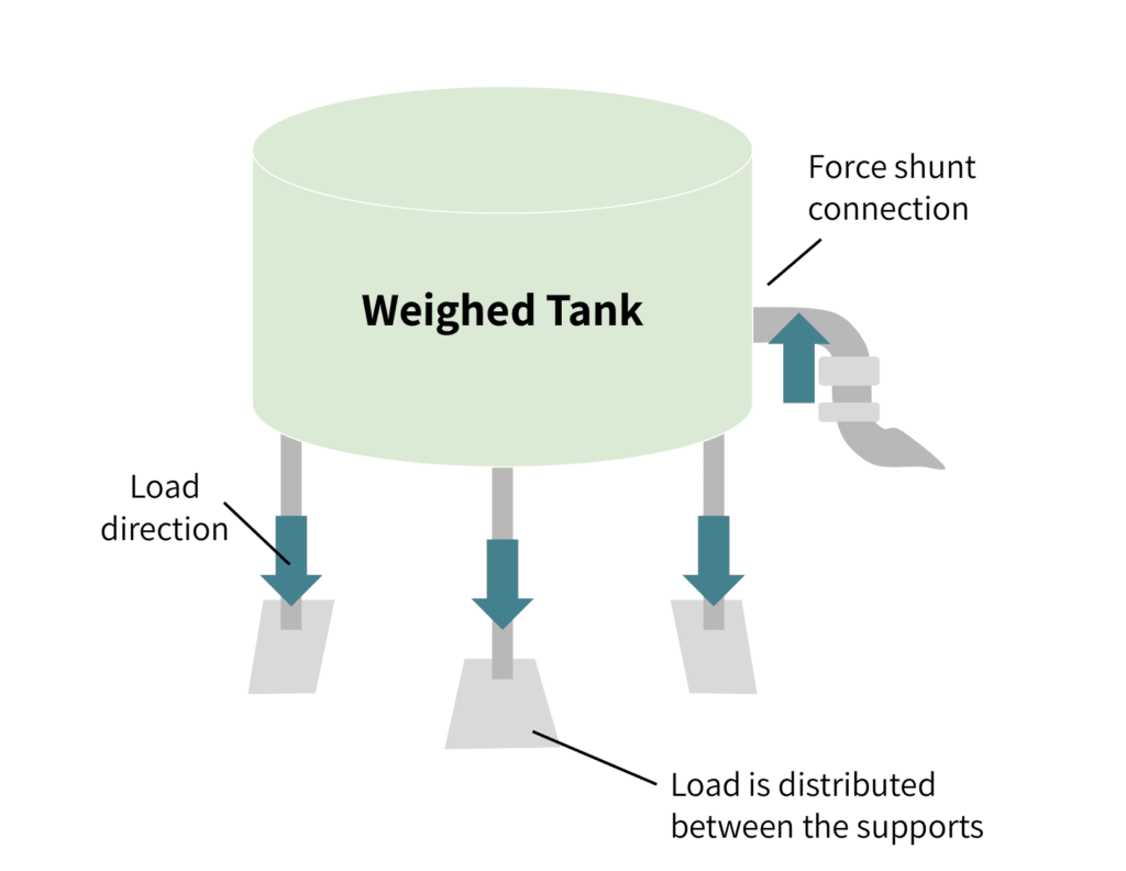
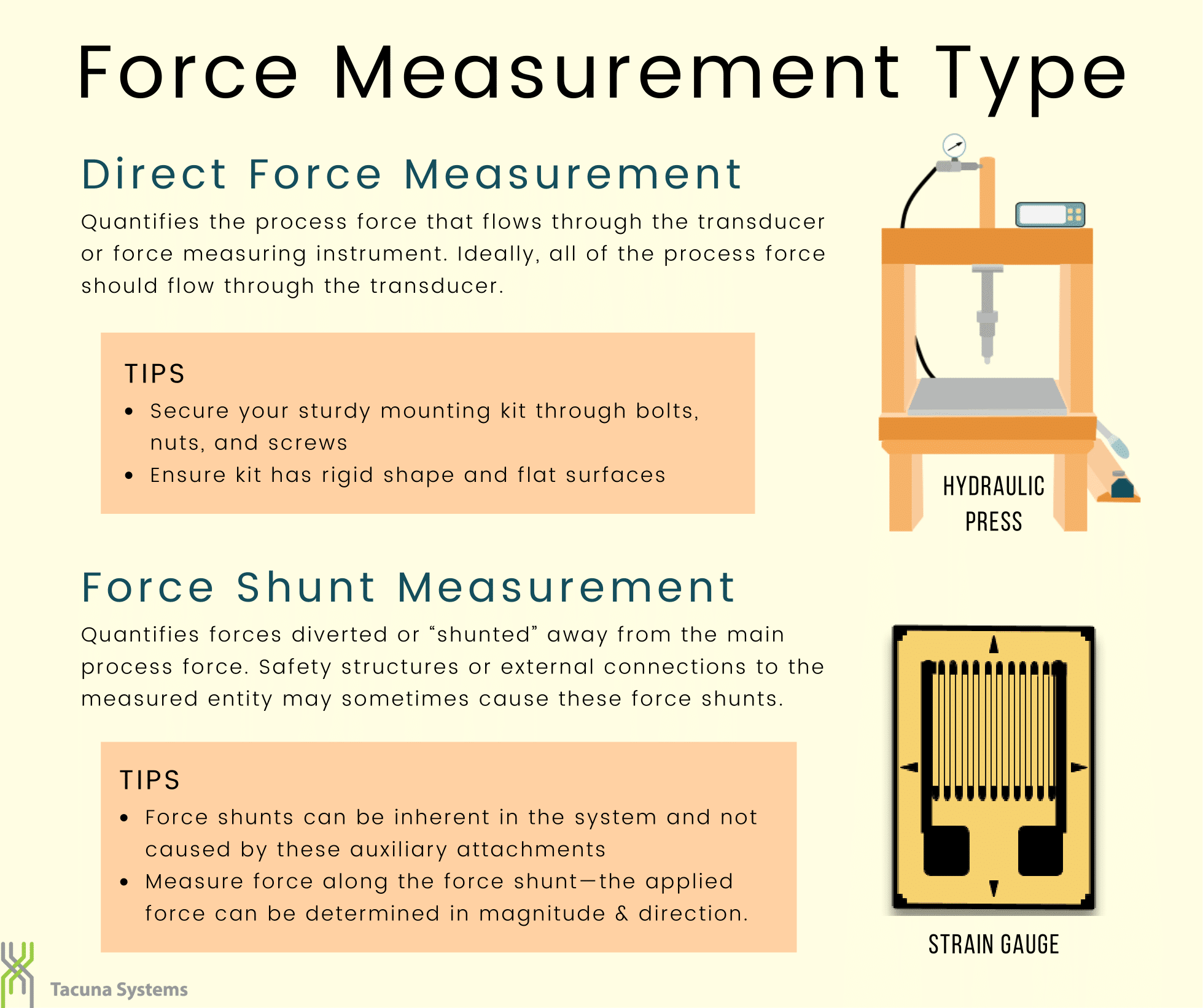
- Direct force measurement quantifies the process force that flows through the transducer or force measuring instrument. Most (ideally all) of the process force should flow through this transducer. For an example see the article Choosing the Right Load Cell For Your Job in our Knowledge Base. A direct force measurement requires the use of mounting kits fixed through bolts, screws, and nuts. The mounting kits must have flat surfaces and be rigid. (See Load Cell Mounting and Installation Best Practices.)
- Force shunt measurement quantifies forces diverted or “shunted” away from the main process force. Safety structures or other external connections to the measured entity may sometimes cause these force shunts. Force shunts can also be inherent in the system and not caused by these auxiliary attachments. Measuring the force along the force shunt enables the derivation of the applied force in both magnitude and direction.
Direct force measurement’s advantage is high accuracy, but sometimes force shunt measurement’s advantages outweigh this. For these applications, one usually designs and deploys special sensors.
Force Measurement Methods
Whereas many force measurement methods have evolved over the years, the most common ones use deformation of a structure. That is, these instruments convert forces to signals using elastic elements.
This section discusses two frequently used, closely related instruments that employ deformation: strain gauges and strain gauge transducers. Both have advantages and disadvantages in measuring force shunts. Note a third method exists: the use of strain washers. However these are predominantly piezoelectric devices not strain gauge technology and therefore not covered in detail here.
The Use of Strain Gauges
Strain gauges can be installed on machinery to directly measure force. For a more comprehensive explanation of strain gauges, see the article The Versatile Strain Gauge Load Cell.
Two types of strain gauges are bonded and unbonded. For measuring force shunts, a bonded strain gauge is the most appropriate. This is because bonded strain gauges have practically no influence on the structure of the object under test. That is, they do not affect the stiffness and the dynamic behavior of the test object as a whole. In this case, the strain gauge is bonded (usually with epoxy) to the actual structure causing the force shunt; it is then covered with some kind of protective coating to avoid environmental degradation of the electronics. Precise installation ensures that only the tensile and/or compressive forces act on the gauge and not any bending moments. This is done at the application site.
Figure 2 below shows a full-bridge strain gauge.
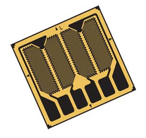
One must carefully select the gauge for each application to compensate for parasitic effects of bending moments or torsion, temperature shifts and other undesirable effects. A strain gauge with a rosette configuration is helpful in these scenarios.
The bridge output signal can be increased by a controlled weakening of the area on the object’s body surface where the strain gauge is attached. However, this affects the object’s stiffness, dynamic behavior, and stability. Moreover, installing a strain gauge on the body of an object in an application can be painstaking and time consuming. Despite the accuracy of this method, its disadvantages may discourage its use.
The Use of Strain-Gauge Transducers
Strain gauge transducers are simply strain gauge load cells. They include the use of strain gauge described above. However they have additional components such as an elastic element (also called the structural member) and a housing unit. See the article, The Versatile Strain Gauge Load Cell for more details on how they operate.
When using these devices, the shunt force created by the support structure (or other test object) acts on this elastic element itself. The elastic element in turn undergoes a strain. Each strain gauge attached to that elastic element then generates an output signal proportional to that strain. Since the bond already exists between the strain gauges and the load cell’s elastic element, installation at the application site is much simpler than bonding individual strain gauges to a test object. Likewise the load cell has the needed coatings and environmental protections built in, eliminating that step in the previous section as well.
On load cells, the strain in the area of the installed strain gauges (at the square hollows in Figure 3) is greater than the strain value between the two screwed connections (bolt holes in Figure 3).

This shows that the strain generated by the force on the load cell concentrates at the precise location of its strain gauge(s). In this case, the force along the force shunt must align with the intended direction of the gauge’s applied force.
The Mathematical Relationship Between Strain and Distance from Application Point:
The mathematical expression for the approximate excessive increase in strain is:
\begin{align*}
\varepsilon_ {SG}&=\frac{\varepsilon_{object}\cdot l_{strain, sensor}}{l_{strain, zone}}\\
\text{Where: } \ \
\varepsilon _{SG} &= \text{Strain present under the strain gauge}\\
\varepsilon _{object} &= \text{Strain between the screwed connections}\\
l _{strain: sensor} &= \text{Distance between the screwed connections}\\
l _{strain: sensor} &= \text{Distance between the screwed connections}\\
l _{strain: zone} &= \text{Length of the area of structural weakening}
\end{align*}
This expression is based on ideal conditions with the assumption that the zone around the application point is strain-free. However, in practical terms, this is not entirely correct.
Furthermore, from the mathematical expression one can infer the load cell’s sensitivity is adjustable through the length ratio of strain zone and the distance between the bolts. Recall the ideal strain zone is at the physical location of the strain gauge. In theory then one can achieve a very high sensitivity.
Advantages and Disadvantages of Force Shunt Measuring Methods
Here we list the advantages and disadvantages of each type force shunt measurement method described above.
Strain Gauges
The advantages of using strain gauges for force shunt measurements are:
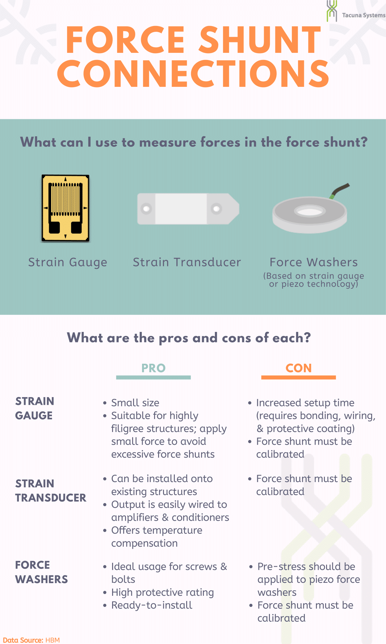
- They are small and occupy very little space
- They are best for highly filigree structures with only small forces on the gauge, since they avoid unintended force shunts that a load cell structural element could create on delicate structures.
Some disadvantages include the following:
- The installation process requires bonding, wiring, protective coating etc.; these all increase installation time.
- It requires calibration of the force shunt to ensure its accurate representation, also increasing setup time.
Strain Gauge Transducers
The advantages of using strain transducers (load cells) are:
- They offer easy installation and rapid deployment at the application site with ordinary recommended hardware.
- The load cell output connects easily to electronics amplifiers and conditioners. (Tacuna Systems offers these devices, optionally bundled with our load cells.)
- These devices are temperature compensated (temperature range is in the load cell datasheet).
The main disadvantage of load cells is that they require calibration at the application site.
Tacuna Systems offers various load cell types not limited to just single point and double-ended load cells. We also offer load cells that lend themselves to a force shunt setup, and optional calibration services to ensure proper setup. Contact us for ideas specific to your application.
The Importance of System Calibration in Measuring Force Shunts
Calibration is the process of comparing a measuring instrument against an authoritative reference (such as certified calibration weights) for the same type of measurement. For measurement accuracy, the device must be calibrated before it goes into service (either before or after installation). Calibration gives a characteristic curve created by graphing the transducer response (output signal) vs. the applied force over a range of values. This curve then serves as a reference for proper maintenance calibration throughout the device’s service life. As with all measured loads, the calibration weights must be axial to the measuring device’s intended direction.
Where force shunts are present, load cell calibration is highly important. It helps to ensure that the instrument is providing an accurate reading of the actual force shunt in the tested object as opposed to other forces present. Also, the load cell’s quality will determine both the reading’s accuracy and the longevity of the load cell’s calibration after repeated uses.
When using load cells/force transducers, high precision calibration can occur before mounting in the field (also called formal calibration). However, for the specific application of force shunt measurement, the recommended practice is to calibrate the load cell directly on the object in the field right after installation. The calibration procedure will involve capturing the output of the load cell when there is zero-load on the shunt. This output is again measured when the maximum rated force is applied along the shunt. The calibration technician then makes the necessary adjustments to the amplifier and readout until the output of the measurement instrument matches the nominal value specified in its datasheet. As with any calibration procedure, it is important to control conditions such as temperature, alignment of load, and humidity as much as possible when calibrating the force shunt.
Read: Calibrating the Force Measuring System.
Conclusion
This article explains the various concepts of force measurement, force shunts, and products in our online shop that are readily available for measuring forces in the force shunt. Both methods discussed have very minimal effects on the dynamic mechanical behavior of the monitored structure as a whole. However, this article recommends strain-gauge-based technology for very high accuracy shunt force measurements.