
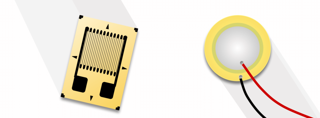
Strain gauge load cells and piezoelectric sensors are similarly practical across industrial applications. However, their differences inform which is the best choice over the other. Performance factors such as resolution, accuracy, and susceptibility to environmental errors, as well as utilization factors such as ease of measurement, signal transmission, equipment interfaces, and physical dimensions, determine the best choice for your system.
Key Takeaways
- Static vs. Dynamic Capability: Strain gauge load cells measure both static weights and dynamic forces, whereas piezoelectric sensors can only measure rapid dynamic forces and high-frequency vibrations, since they experience dielectric charge decay.
- Stiffness & Bandwidth: Piezoelectric ceramics have both high material stiffness and high natural resonant frequencies (up to 100 kHz), making them ideal for impact, shock wave, and modal vibration analysis.
- Bridge vs. Charge Amplification: Strain gauge load cells rely on Wheatstone bridge excitation and mV/V signal conditioners, whereas piezoelectric sensors require high-impedance charge amplifiers or internal IEPE/ICP microelectronics.
- Charge Circuit Mechanics: Charge amplifiers use operational feedback (\(R_F \cdot C_F\)) to establish a fixed calibration factor, tune dynamic frequency response, and eliminate measurement errors caused by stray cable (\(C_c\)) and sensor (\(C_P\)) capacitance.
- Thermal & Curie Limits: Synthetic ceramics like Lead Zirconate Titanate (PZT) account for over 70% of piezoelectric sensors, but permanently depole and lose signal output if exposed to temperatures above their Curie threshold (\(T_c\)).
- Comparison Matrix: Review key differences between the two sensor types.
The Physical Principles Behind Strain Gauge and Piezoelectric Sensor Operation
Strain gauge and piezoelectric sensors both convert forces to electrical signals using different physical properties. Here, we briefly explain both.
Strain Gauges
A strain gauge sensor transforms an applied force to an electrical signal through elastic deformation of the strain gauge. (See The Versatile Strain Gauge Load Cell for more information.) These forces (such as weight, acceleration and pressure) can be static or dynamic in nature. When a tensile force is parallel to the gauge’s thin wiring, the wire lengthens and narrows (much like pulling a rubber band). This increases the resistance in the gauge. Likewise, a parallel compressive force widens and shortens the wire, decreasing resistance. With either force direction, the change in the material’s electrical resistance is proportional to the magnitude of the applied force.
The following mathematical formula expresses the proportionality of force to change in resistance within the gauge:
\begin{align*}
\large{R}\pm \Delta R&=\rho \cdot \left ( \frac{L\pm \Delta L}{A \pm \Delta A} \right )\\ \\
\text{Where: }\\
R &=\text{ Resistance (in units of ohms, } \Omega \text{)} \\
\rho &=\text{ Resistivity (a constant in units of ohm-meter, }\Omega{m} \text{)} \\
L &= \text{ Length in meters (m)} \\
A &= \text{ Cross sectional areas in meters squared } (m^{2}) \\
\Delta A &= \text{ Change in cross sectional area in meters squared (}m ^2 \text{)} \\
\Delta {R} &= \text{ Change in resistance in ohms (} \Omega \text{)} \\
\Delta L &= \text{ Change in length in meters (}m \text{)} \\
\end{align*}
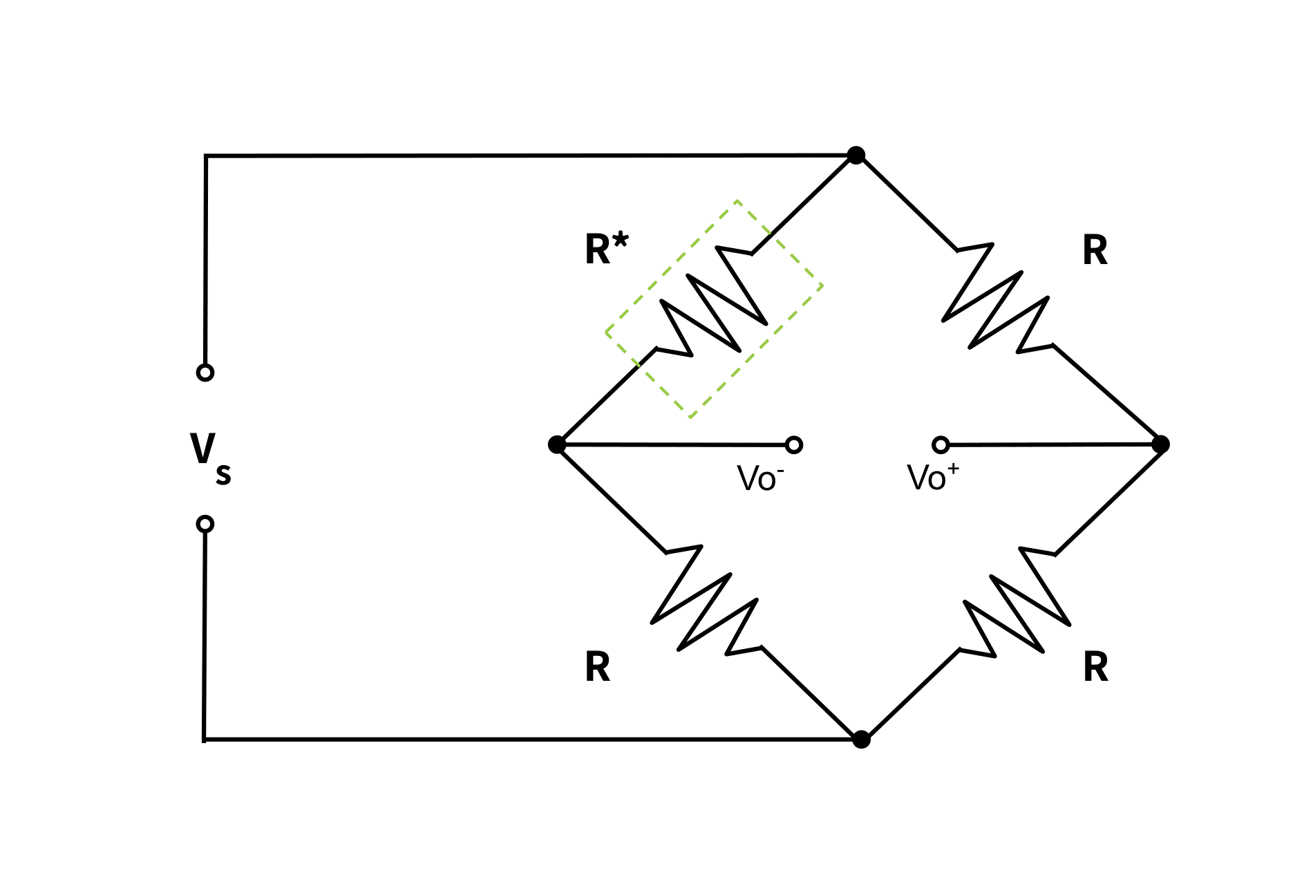
The load cell’s output signal is the voltage drop across this small change in resistance. Although tiny, the signal is measurable due to the cell’s internal Wheatstone bridge circuitry. The mathematical formula for one such circuit, the Quarter Bridge (depicted in Figure 1), appears below. See The Versatile Strain Gauge Load Cell for a more detailed explanation of bridge circuitry, including half- and full-bridge configurations that contain added gauges for temperature and non-axial load compensation.
\(\large V_{o}=\frac{V_{s}dR}{4R}\)
Because the analog output voltage is too small to be display-readable (of the order of mV) and vulnerable to signal noise, it must undergo filtering and amplification. For more on this topic, see Why Do I Need An Amplifier (and Other Signal Conditioners)?
Piezoelectric Sensor
Piezoelectric sensors convert forces into an electrical charge (\(q\)) through the elastic deformation of asymmetrical crystals or polarized ceramics. Applying a load shifts the material’s internal electrical dipoles (see Figure 2), generating surface charges proportional to the force across opposing electrode plates.
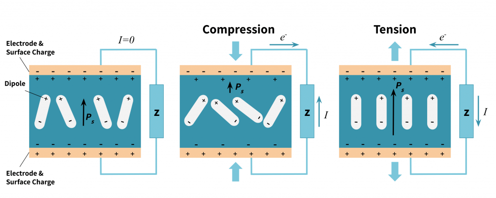
The leftmost drawing in Figure 2 shows a piezoelectric sensor in steady state. The internal material has dipoles (indicated by \(P_{s}\) with magnitude indicated by the length of the arrow) that create surface charges on the sensor’s plates. Under compression, this polarity weakens; the positive surface charge attracts electrons in the wire and the negative repels them, creating a current with the same polarity as the material’s dipole. Under a tensile force, the material polarity strengthens, the plate surface charges are relatively weaker, and a current forms opposite the dipole’s orientation. This phenomenon is dynamic—the charge difference dissipates quickly.
Unlike strain gauges that require an excitation voltage, piezoelectric sensors generate their own electricity when under pressure. However, supplying them with an alternating voltage induces vibration in the crystal, producing a “reverse piezoelectric effect“. Ultrasonic actuators, among other applications, exploit this reverse effect.
Since surface charges naturally dissipate through the circuit’s finite insulation resistance, piezoelectric sensors cannot maintain a steady signal under constant pressure. They measure strictly dynamic forces such as rapid pressure spikes, impact shocks, and high-frequency vibrations, where the rate of change of the force exceeds the charge decay rate.
The magnitude of the generated charge (\(q\)) is expressed by:
\(q=a\cdot F\cdot K_{s}\)
where \(q\) is the generated electrical charge in Coulombs, \(F\) is the applied force in Newtons, \(K_{s}\) is the mechanical spring rate in \(m/N\), and \(a\) is the piezoelectric material constant in \(C/m\).
Because this output is an ultra-high-impedance charge (typically measured in picocoulombs, \(\text{pC}\)), it cannot be read directly by standard strain load cell instrumentation or standard voltage DAQs. Instead, it requires a specialized charge amplifier (or internal IEPE/ICP microelectronics). The charge amplifier converts the signal into a stable, low-impedance voltage while simultaneously isolating it from cable capacitance and charge leakage.
The Materials at the Core of Strain Gauge vs. Piezoelectric Sensors
With the exception of sealants and insulators, strain gauge sensors exploit the mechanical strain of metals. At their core is the gauge, which uses thin-film conductive materials such as copper-nickel, nickel chromium, and platinum-tungsten alloys. (If the gauge is a semi-conductor instead, then silicon material is used.) This material is etched onto a non-conductive material such as a polymer, and bonded to a metal spring element.
Piezoelectricity naturally occurs in crystals like Rochelle salt and quartz. However, many piezoelectric crystals in sensors are one of two types of synthetics: (1) crystalline such as Lithium Sulphate and Ammonium Di-Hydrogen phosphate, and (2) polarized ferroelectric ceramics such as Barium Titanate and Lead Zirconate Titanate (PZT). This second category is the industry-standard material in modern piezoelectric transducers due to its high sensitivity and temperature stability. In fact, PZT ceramics account for over 70% of modern industrial piezoelectric force sensors and accelerometers.
Sensor Fabrication and Resulting Engineering Constraints
The manufacturing processes used for strain gauges and piezoelectric elements dictate their operating limits, thermal stability, and long-term reliability. Here, we take a closer look at how their construction affects these functional limitations.
Strain Gauges
Most strain gauge fabrication uses photolithography and chemical etching to bond its conductive foil grid to the thin polymer backing. As explained previously, the gauge is then carefully bonded within a precision-machined, metal elastic element using high-grade epoxy or phenolic adhesives. Lastly, the gauge is then hermetically sealed in the flexure cavity to protect it against external mechanical and chemical damages.
Engineering implications: The sensor’s long-term accuracy depends greatly on the bond’s and seal’s integrity. Improper bonding can cause adhesive creep, zero-drift, or hysteresis under sustained static loads, especially under thermal cycling. Poor seal integrity introduces moisture, which permanently damages the device.
Piezoelectric Sensors
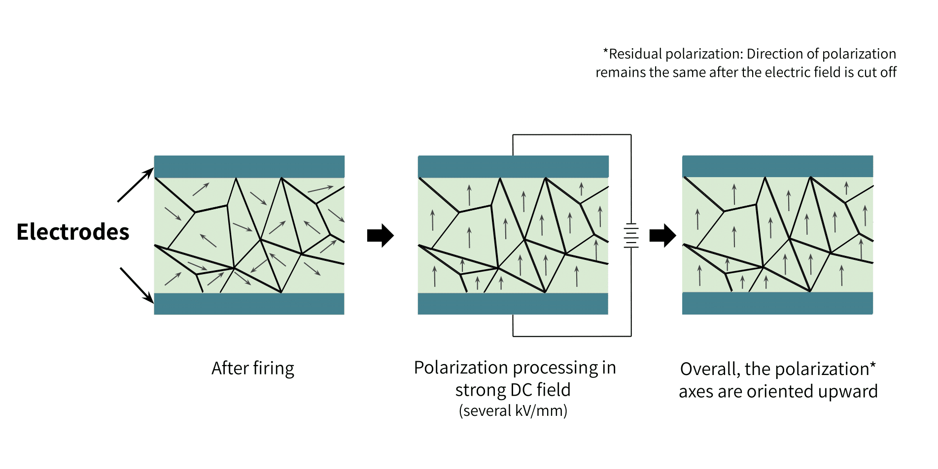
While natural quartz crystals are precision-cut along specific crystallographic axes, synthetic ferroelectric ceramics (such as PZT) must undergo a process called poling (Figure 3). This process involves first sintering ceramic powder into a shape, then heating it to a temperature above its Curie point (the temperature where the crystal’s ferroelectric properties break down). Next, a strong DC electric field of several kV/mm is applied to the heated material, forcing its randomized dipoles to align. Finally, the material cools, still under the electric field, locking the parallel dipole orientation in place.
Depending on the sensor’s coupling mode (such as 33-mode vs. 31-mode), the applied stress can act parallel or perpendicular to the crystal’s polarization axis. Figure 4 below depicts the 31-mode coupling.
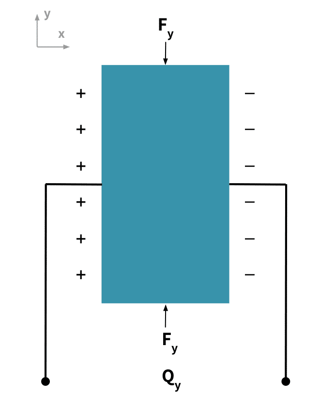
Engineering implications: Natural piezoelectric materials are more simple to fabricate, but synthetic piezoceramics are more stable and therefore offer far higher sensitivity. The caveat of synthetic crystals is that they become permanently depoled when exposed to temperatures exceeding their Curie limit, causing a total loss of signal output.
Form Factors of Strain Load Cells vs. Piezoelectric Sensors
The form factor of strain gauge load cells produces their versatility. That is, their elastic elements can take on a wide range of shapes to guide the load precisely through the gauge position, capturing strains at an exact location within a measurement system. By convention, the geometric shape of the gauge’s structural housing unit gives the load cell it’s name, such as tension link, S-beam, canister, or planar beam. This diversity makes strain gauge load cells highly adaptable to the needs of different applications.
Generally, piezoelectric sensors have more compact and rigid housings than those of strain gauges. Their small size (usually washer or button form factors) and excellent dynamic response makes them suitable for highly sensitive applications. They have wide uses from medical robotics to acoustics applications.
Both types of sensors function well in multi-axial applications, and can support compression, shear, or bending stresses.
Amplification: Bridge Amplifiers vs. Charge Amplifiers
Strain gauge load cells produce millivolt signals that require amplification prior to displaying readings or feeding the signal into data processors or control systems. We cover these devices extensively in our guides, Why Do I Need a Load Cell Amplifier (and Other Signal Conditioners)? and How to Reduce Noise in Load Cell Output Signals. Here, we will focus on the charge amplifiers that boost piezoelectric sensor output.
Piezoelectric Charge Amplifiers
The charge amplifier is an electronic circuit that converts the charge output from the piezoelectric sensor to a voltage output. The design includes an operational amplifier with a high input impedance (usually a MOSFET input stage), a suitable frequency response, and a low output impedance. The charge amplifier also uses a feedback technique to provide gain adjustment and signal filtering.
Figure 5 below shows the schematic of the charge amplifier connected with the modeled cable and sensor.
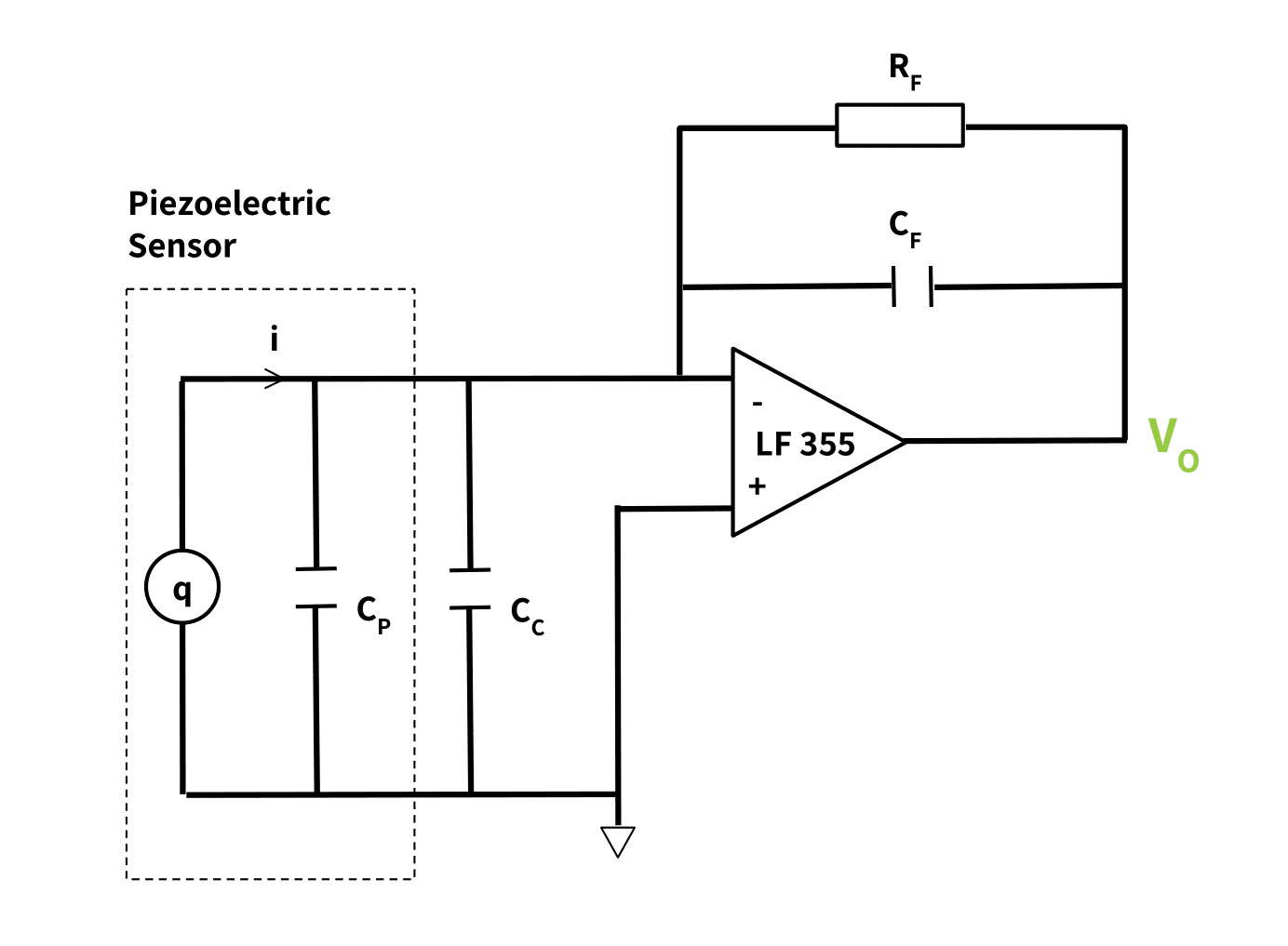
In the diagram, \(q\) is the charge source in parallel with the sensor capacitance \(C_{P}\) ; \(C_{c}\) is the cable capacitance which is also in parallel with the sensor parameters; \(C_{F}\) and \(R_{F}\) are the feedback capacitance and resistance respectively. (Figure 2 in our guide, Installing and Mounting Piezoelectric Sensors, models an effective resistance of these devices in series with this parallel capacitance \(C_{P}\). It is this resistance that causes charge leakage.)
The Charge Amplifier: How its Design Affects Measurement Quality
This type of charge amplifier design ensures:
- A calibration factor fixed by the value of the feedback capacitance and resistance \(C_{F}\) and \(R_{F}\).
- An adjustable dynamic frequency range as the time constant (\(R_{F}\) * \(C_{F}\)), but only for dynamic loading. (It can be made large or small for low and high-frequency operations respectively.)
- Eliminated effects of stray capacitances from the connecting cables \(C_{c}\) and the sensor \(C_{P}\).
These three results give the piezoelectric transducer a high stability, wide dynamic range, good temperature stability, good linearity, and low hysteresis.
The output terminal of the charge amplifier can then connect to an analog-to-digital and signal processing component; or it can connect to a voltage meter.
Performance Specification Differences
As expected, the electrical specifications provided on original equipment manufacturers’ (OEM) datasheets differ for these two sensor types. The main differences are as follows.
- Rated Capacity: Strain gauge load cells cover ultra-broad ranges from micro-loads to multi-meganewton industrial capacities (5 N to >40 MN). Piezoelectric sensors typically span 5 kN to 1 MN.
- Static vs. Dynamic Response: Strain gauges measure both static loads (holding tare indefinitely) and dynamic forces up to ~1 kHz. Piezoelectric sensors measure strictly dynamic forces (vibrations, impacts, rapid transients) due to continuous charge decay.
- Creep & Output Drift: Strain gauges exhibit minimal creep under sustained static loads. Piezoelectric outputs drift rapidly under constant pressure as charge bleeds across the dielectric, making true static weighing impossible.
- Stiffness & Resonant Frequency: Piezoelectric elements are extremely stiff, yielding high natural resonant frequencies up to 100 kHz. Strain gauge load cells deform elastically and have lower natural frequencies.
- Sensitivity & Signal Rating: Strain gauge output depends on bridge excitation and full-scale rating, expressed in millivolts per volt (mV/V). Piezoelectric sensitivity depends on crystal geometry and material constants, rated in picocoulombs per Newton (pC/N).
- Linearity & Hysteresis: Strain gauge load cells offer superior linearity and lower hysteresis across their full rated range compared to piezoelectric transducers.
- Environmental Sealing & Thermal Drift: Both sensor types support IP67 to IP69K hermetic seals for harsh operating environments. Compensation for thermal sensitivity is via self-temperature-compensating (STC) foil patterns in strain gauges, or charge amplifiers/conditioners in piezoelectric systems.
Strain Gauge vs. Piezoelectric Sensors: A Summary Comparison Table
| Feature / Metric | Strain Gauge Transducers (Load Cells) | Piezoelectric Force Sensors |
|---|---|---|
| Operating Principle | Resistance change (\(\Delta R\)) via elastic foil strain | Electric charge (\(q\)) generated by crystal deformation |
| Measurement Capability | Static & Dynamic (DC to ~1 kHz) | Dynamic Only (AC high-frequency up to 100 kHz) |
| Long-Term Drift (Creep) | Extremely low; holds tare indefinitely | High charge leakage over time; cannot hold static tare |
| Sensitivity & Stiffness | Moderate stiffness; depends on flexure element | Extremely high stiffness and high natural frequency |
| Signal Conditioning | Wheatstone bridge excitation & mV/V amplifiers | High-impedance charge amplifiers or ICP/IEPE conditioning |
| Primary Industrial Use | Scale weighing, structural test rigs, vessel siloing | Impact testing, shock wave monitoring, modal vibration |
Summary & Application Guidelines
Both strain gauge and piezoelectric force transducers are of undeniable importance to many force measurement applications. Piezoelectric sensors are ideal for measuring highly dynamic transients, shock impacts, or high-frequency vibrations (>1 kHz) within space-constrained assemblies. For static weighing, vessel silos, structural load testing, and any application requiring long-term zero stability without charge decay, strain gauge load cells remain the industry standard due to their widely available form factors, linear output, resistance stability, and standard Wheatstone bridge signal conditioning.
To compare specific strain gauge load cell element geometries, explore our guide, Choosing the Right Load Cell for Your Job, or contact Tacuna Systems’s engineering team for custom load measurement support.
Other Resources:
- Force Measurement Glossary
- Force and Weight Measurement Resources
- An Overview of Load Cells
- The Versatile Strain Gauge Load Cell
- Connecting a Force Sensor to a DAQ
- External Wiring in Strain Gauge Load Cells
- How to Read a Load Cell Datasheet
References
- Piezoelectric Sensor, A Method for manufacturing a piezoelectric sensor and a medical implantable lead comprising such a sensor, US 8,626,313 B2
- Comparative look at strain gauge and piezoelectric sensors by JAC Chapman, Elexsys
- The Instrumentation Reference Book, Edited by Walt Boyes.
- Jayant Sirohi, Inderjit Chopra , “Fundamental Understanding of Piezoelectric Strain Sensors,” Journal of Intelligent Material Systems and Structures.
- Market.us, Global Piezoceramic Sensor Market Report.