
As science and engineering improve, technology and materials become lighter, faster, stronger, and more efficient. The need for smaller and more reliable instrumentation grows as fast as the technology industry using it. This has driven the development of, among other things, optical strain gauges. Optical strain gauges offer a low-profile solution to measure strains over large surfaces, allowing for further advances in instrumentation capability.
An optical strain gauge, or fiber optic strain sensor, is a device that uses fiber optical technology to measure the strain on an object. It detects changes in light transmission when the object attached to it experiences a load. Its small size, often the diameter of a human hair, makes it practical in tight spaces. Yet it also possesses the ability to measure thousands of locations over several meters.
Key Takeaways
- Optical strain gauges use fiber optic technology to measure strain efficiently across large surfaces.
- They detect changes in light transmission to quantify loads in various environments without needing electricity.
- Advantages include the ability to be embedded in structures and resistance to electromagnetic interference.
- Applications range from monitoring civil structures to detecting small defects in aircraft parts and wind turbines.
- Optical strain gauges are increasingly replacing traditional gauges, expanding their use in structural health monitoring.
Fiber Optic Technology
Fiber optic cables, or fiber optic lines, are very thin strands of glass capable of transmitting signals across long distances. They have revolutionized the way people access the Internet, view television, and even make phone calls.
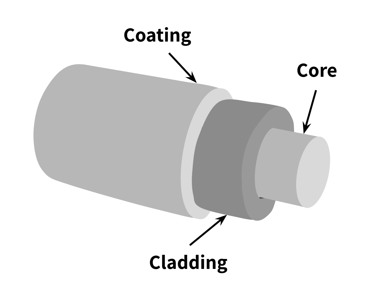
Fiber optic lines consist of three main parts (See Figure 1). The core is a bundle of hair-thin glass strands that transmit a signal via light waves. The cladding is a reflective glass that bounces light waves back into the core. This is critical for signals to travel long distances even though the cable is not perfectly straight. Lastly, the buffer is a protective coating of plastic or rubber that prevents environmental damage.
Strain
When an object experiences an applied force, it has a tendency to change shape. This is called deformation. Picture a fishing pole bending under the weight of a fish, or a rubber ball flattening when a person steps on it. These bodies deform when they bear large enough loads.
This deformation of objects is the primary principle strain gauges use to quantify loads and forces. Strain is defined as the ratio of the change in length of a material in the direction of an applied force, to the original length in that direction.
A strain gauge quantifies a load on an object via a change in its output signal vs. the signal when the object under no load. This is true for both electronic strain gauges and optical strain gauges. The exact relationship of strain to load is a function of the known material properties of a load-bearing object.
Design of Optical Strain Gauges
For the fiber in an optical strain gauge to effectively detect changes in strain, its design must differ from conventional fiber optic lines for telecommunications. That is, the core of the cable undergoes inscription (a process of laser etching) during production. These inscriptions are arranged in unique patterns called Fiber Bragg Gratings, or FBGs. They create material interference in the fiber, reflecting light differently than the rest of the core.
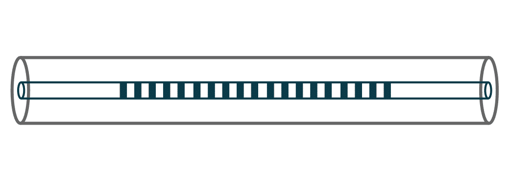
Think of each core strand as an extremely long glass cylinder. The FBGs behave like windows spaced out through the cylindrical fiber. When light from a laser hits each window, certain wavelengths pass through, while others reflect. When the FBGs change shape due to strain, there will be a measurable difference in the light waves transmitted. The interval between each window or inscription is critical for recording strain. Figure 2 shows a simplified depiction of a Fiber Bragg Grating.
When the fiber is in tension, or stretched, it experiences positive strain. This means the interval between each inscription lengthens. Similarly, when the fiber undergoes compression, these gaps shorten, and the strain is negative.
Placing two FBGs in opposite directions allows one to read compression with its counterpart reading tension. This has benefits including partial compensation for temperature effects, because both gauges will be affected by the same thermal expansion.
Advantages and Disadvantages of Optical Strain Gauges
Strain gauges that use fiber optic technology offer several advantages over their electrical counterparts. For one, they do not need electricity or an excitation voltage to operate. This makes them suitable for environments that will experience high levels of electromagnetic interference.
Also, because they have a slim profile, they can either be embedded in structures during production, or discretely attached to the structure’s surface. When fiberglass composites or carbon fiber with resin make up the optical strain gauge, a manufacturing process can easily embed the single inscribed fiber optic strand into a structure during manufacture. This allows for internal strain measurements unattainable with conventional strain gauges. A practical application of this is in the production of aircraft structures. In these applications, an array of such embedded optical fibers enable the real-time measurement of forces on these aircraft components.
On the other hand, the materials in optical/fiber-optic strain gauges have a relatively high coefficient of thermal expansion. Because of this, they often need to be combined with temperature sensors to compensate for temperature in their measurements.
Optical Strain Gauge Applications
Recall conventional strain gauges use an electrical element that measures a change in its resistance proportional to the mechanical strain induced by an applied force. While optical strain gauges employ a different technology than this, they can be used for similar applications.
One common application of optical strain sensors is the monitoring of long-term civil structures like bridges, buildings, tunnels, and pipelines. Long fiber-optic lines allow the distributed sensing of strain localization. As discussed in the article, Advantages and Applications of Wireless Load Cells, continuous monitoring of loads on the structure can help pinpoint damage, improve the life of the structure, and automate maintenance and inspection time.
Optical strain gauges can detect small cracks and material defects in other structures as well. Because of this they are important in static and fatigue testing of components such as aircraft parts and wind turbine blades.
Optical strain gauges or fiber-optic sensors measure more than just strain. They also serve as pressure sensors, temperature gauges, and vibration transducers.
Conclusion
The optical strain gauge is a versatile alternative to conventional electronic strain gauges. While electronic strain gauges are a mature technology, optical strain gauges continue to develop capabilities in defect detection on large buildings and structures, FEA model validation, and structural health monitoring of composite materials. They continue to be a developing technology in instrumentation. And their uses and applications are constantly expanding.
References
- Handbook of Optical Sensors José Luís Santos, Faramarz Farahi
- Measurement and Instrumentation Principles, 3rd Edition Alan S. Morris.
- Optical frequency domain reflectometry: principles and applications in fiber optic sensing, Stephen T. Kreger, Nur Aida Abdul Rahim, Naman Garg, Sandra M. Klute, Daniel R. Metrey, Noah Beaty, James W. Jeans, and Robert Gamber
- Three-Axis Distributed Fiber Optic Strain Measurement in 3D Woven Composite Structures, Matt Castelluccia, Sandra Klutea, Evan M. Lallya, Mark E. Froggatta, David Lowryba