
When you shop for an OIML-certified load cell, you will see an “accuracy class” on its data sheet. This specification gives an immediate shorthand for its precision and intended application. In this article, we summarize the performance tolerances and environmental benchmarks required for each class to help you find the right sensor for your specific technical requirements.
For more information on OIML’s Recommendation 60-1 governing load cells, see the latest published OIML requirements. For U.S.-specific guidance, see our companion article: Load Cell Classes: NIST Requirements.
Key Takeaways
- OIML Standards: This article covers the international performance benchmarks for load cells defined in Recommendation 60-1 (R60-1).
- Accuracy Hierarchy: OIML defines four accuracy classes (A, B, C, and D) based on measuring range and verification intervals.
- Performance Benchmarking: Each class requires specific tolerances for non-linearity, hysteresis, and temperature effects to earn certification.
- The Certification Guarantee: Manufacturers must prove designs meet these tolerances in approved labs before they can be certified for market.
- Application Alignment: Understanding these classes is the key to balancing cost with the precision required for legal-for-trade or industrial applications.
- NIST vs. OIML: While OIML is the international standard, the NIST Handbook 44 governs similar requirements specifically for the U.S. market.
Why Do Load Cell Classes Exist?
In Measurement Uncertainty in Force Measurement, we discussed the standards-body-approved procedures for mathematically calculating the total measurement uncertainty for a given load cell. These procedures are based on three things:
- very specific environmental conditions, with
- very specific laboratory test equipment, and
- traceable to a primary standard.
While this highly precise lab testing of every load cell is ideal, it’s costly and impractical for large-scale manufacturing. Standards bodies like OIML address this by establishing load cell classes, or categories with specific performance benchmarks.
What proof do we have that a load cell meets these tolerances? Certification testing and approval provide that assurance. For a measuring device (load cell or scale) to earn certification, its manufacturer must submit a test sample of each new model to an approved laboratory. The load cell model receives certification when testing shows that it meets all the performance requirements for its class.
What Standards Bodies Govern Load Cell Certifications?
This article covers the requirements published by the International Organization of Legal Metrology (known as OIML from the organization’s name in French) in its Recommendation 60-1 (abbreviated R60-1). Its companion article, Load Cell Classes: NIST Requirements, will cover similar requirements by the US Department of Commerce’s National Institute of Standards and Technology (NIST) Handbook 44. Together, these documents form the standards backbone of the global load cell industry.
Background Concepts: Load Limits, Measuring Ranges and Verification Intervals
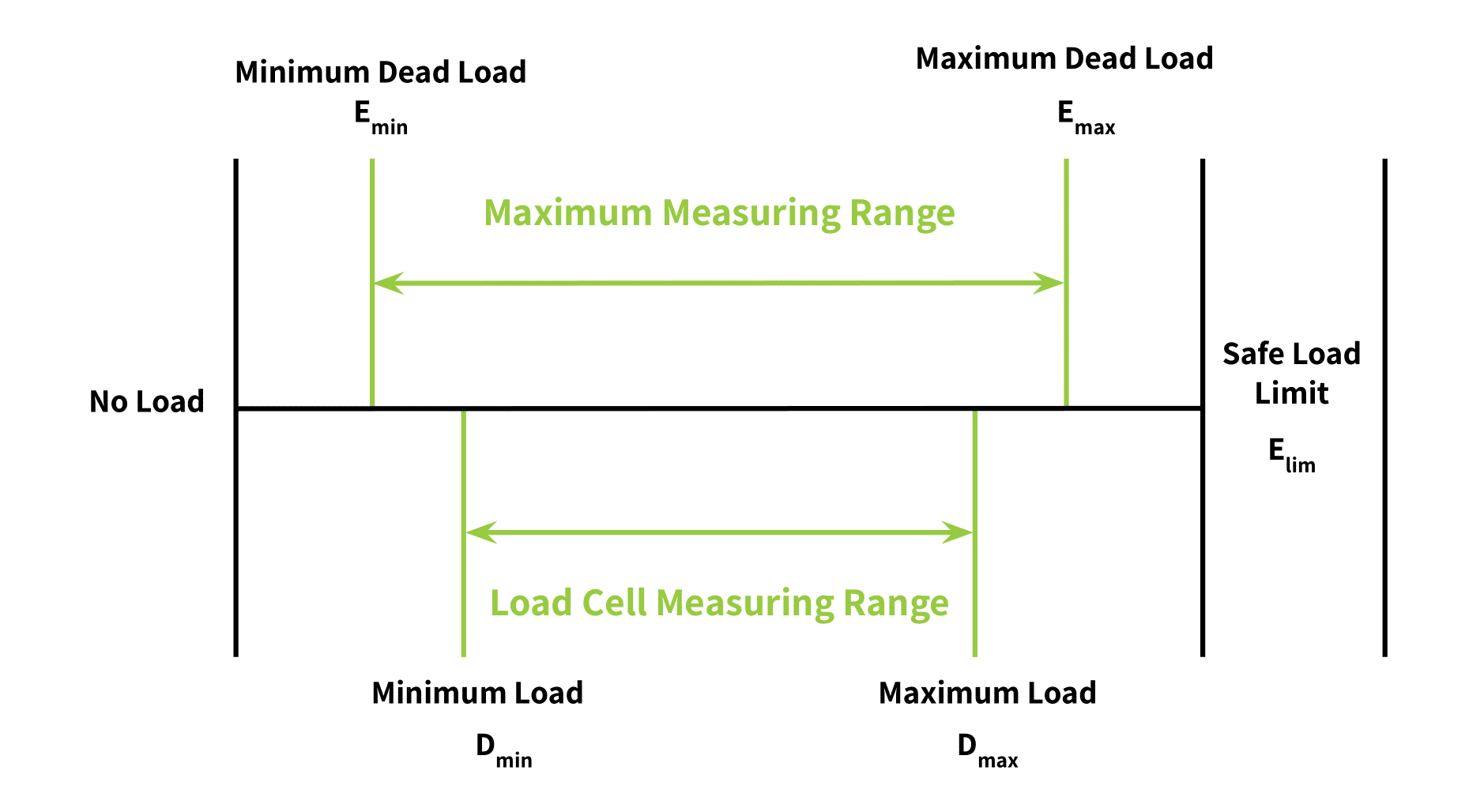
First, we introduce the specific symbols and terms in load cell requirements that describe load cell capacity and safety thresholds. Figure 1 depicts them for further clarity.
Load Definitions
The common symbols used to describe loads and their definitions appear below.
Term
Symbol
Definition
Minimum Dead Load
\(E_{min}\)
The smallest load (expressed in mass units) that can be applied to a load cell while maintaining accurate performance.
Minimum Load of the Measuring Range
\(D_{min}\)
The smallest load (expressed in mass units) applied to the load cell during testing. It is required to be within 10% of \(E_{min}\) .
Maximum Capacity
\(E_{max}\)
The largest load (expressed in mass units) that can be applied to a load cell, per the manufacturer’s specifications. It is usually about 2/3rds of the safe load limit, \(E_{lim}\).
Maximum Load of the Measuring Range
\(D_{max}\)
The largest load (expressed in mass units) applied to the load cell under test, and is required to be within 90% of \(E_{max}\).
Safe Load Limit
\(E_{lim}\)
The greatest load (expressed in mass units) that can be applied to the load cell without permanently changing the performance of the load cell. It is usually 150% of \(E_{max}\).
Measuring Range Definitions
The common expressions for load cell measuring ranges are given below.
Term
Symbol
Definition
Load Cell Measuring Range
\(D_{max} – D_{min}\)
The range of mass values used for certification testing.
Maximum Measuring Range
\(E_{max} – E_{min}\)
The maximum range of mass values a load cell can accurately measure.
Verification Interval Definitions
The concept of a verification interval is important to the definition of load cell classes. The common related terms are as follows.
Term
Symbol
Definition
Load Cell Verification Interval
\(v\)
The quantity (expressed in units of mass) that the load cell measuring range is divided into for testing. It must be larger than \(v_{min}\).
Minimum Load Cell Verification Interval
\(v_{min}\)
The smallest quantity (expressed in mass units) that the maximum measuring range can be divided into. This is a hardware limitation; that is, it represents the smallest change in weight the load cell can reliably “see” without the signal getting lost in thermal drift or electronic noise.
Maximum Number of Load Cell Intervals
\(n_{LC}\)
The maximum number of divisions that the maximum measuring range (\(E_{max} – E_{min}\)) can be divided into. Note \(v \times n_{LC}\) = the maximum measuring range. This quantity is derived from the testing divisions. For example, if a load cell with a maximum measuring range of 3000kg is tested to read in 1kg increments, \(n_{LC}\) = 3000.
Other Important Terms
Term
Apportioning Factor
Symbol
\(p_{LC}\)
Definition
A unit-less multiplier applied to an observed measurement error to quantify the portion of that error attributable to the load cell alone. It assumes the cables, junction boxes, signal conditioners, and readout contribute to the detectable measurement error, to a lesser but still significant degree.
OIML uses a default apportioning factor of 0.70 when the exact value is unknown, since on average, the load cell accounts for 70% of the observed error in a measurement.
A Word About Requirements Scope
The OIML R60 specifications outlined below govern the load cell from the weighing platform to its electrical output, whether analog or digitized via ADC. That is, their scope focuses exclusively on the performance benchmarks of the individual load cell.
These standards do not account for errors introduced by downstream components, such as:
- Signal conditioners or amplifiers
- Data storage devices
- System readouts and displays
For requirements regarding the performance and tolerance of a comprehensive weighing system, refer to OIML R76, Non-automatic Weighing Instruments. While R76 addresses the integrated system, R60 strictly applies to the sensor’s raw output.
OIML R60-1 Load Cell Class Definitions
OIML categorizes load cells into the following four accuracy classes depending on the granularity of measurements in their maximum measuring range. They are: Class A, Class B, Class C, and Class D. Class A load cells are the most granular or accurate, having the highest number of load cell verification intervals in their maximum measuring range, whereas Class D load cells have the fewest intervals.
Which class is appropriate for your application? A general rule of thumb is:
| Ultra-precision applications: Laboratories or Scientific Studies | Class A |
| High-precision applications: Fine Jewelry Trade, Small-Scale Precision Measuring (such as for chemical manufacturing) | Class B |
| Standard Industrial Weighing | Class C |
| Basic Weighing, Some Agricultural Scales | Class D |
The remainder of this section defines other OIML-required load cell performance limits per class.
Load Cell Verification Intervals Per Load Cell Class
The table below (Table 1 in [1]) gives the range of load cell verification intervals per load cell class.
Table 1: Maximum Number of Load Cell Verification Intervals, \(n_{LC}\) , by Accuracy Class
| Class A | Class B | Class C | Class D | |
| Lower Limit | 50,000 | 5,000 | 500 | 100 |
| Upper Limit | Unlimited | 100,000 | 10,000 | 1,000 |
Maximum Permissible Error Per Load Cell Class
The maximum permissible error (MPE) of each load cell accuracy class is calculated per the table below.
Table 2: Maximum MPE On Type Evaluation by Accuracy Class (Table 4 in [1])
| MPE (+/-) | Load, m (expressed in v) | |||
|---|---|---|---|---|
| Class A | Class B | Class C | Class D | |
| pLC × 0.5v (0.35v) |
0 ≤ m ≤ 50,000v | 0 ≤ m ≤ 5,000v | 0 ≤ m ≤ 500v | 0 ≤ m ≤ 50v |
| pLC × 1.0v (0.70v) |
50,000v < m ≤ 200,000v | 5,000v < m ≤ 20,000v | 500v < m ≤ 2,000v | 50v < m ≤ 200v |
| pLC × 1.5v (1.05v) |
200,000v < m | 20,000v < m ≤ 100,000v | 2,000v < m ≤ 10,000v | 200v < m ≤ 1,000v |
This limit encompasses errors due to non-linearity, hysteresis, and temperature effect on sensitivity within the range \(-10^{\circ}\) to \(+40^{\circ}\) C, unless special limits apply per Section 5.6 of [1].
Example: Calculating MPE for a Class C3 Load Cell
To understand how to apply Table 2, consider a common industrial Class C3 load cell with a capacity \(E_{max}\) of 3,000 kg.
First, determine \(v\), the Verification Interval: Divide the capacity by the intervals, \(n_{max}\), which in this case is also 3000: $$v = 3,000\text{ kg} / 3,000 = \mathbf{1\text{ kg}}$$
Second, apply the Apportioning Factor \(p_{LC}\): Assume the default value of 0.7 to account for the load cell’s share of the system error.
Third, calculate the stepped Maximum Permissible Error limits: Based on the load ranges for Class C:
- Loads 0 to 500 kg: \(0.7 \times 0.5 \times 1\text{ kg} = \mathbf{\pm 0.35\text{ kg}}\)
- Loads 501 to 2,000 kg: \(0.7 \times 1.0 \times 1\text{ kg} = \mathbf{\pm 0.70\text{ kg}}\)
- Loads 2,001 to 3,000 kg: \(0.7 \times 1.5 \times 1\text{ kg} = \mathbf{\pm 1.05\text{ kg}}\)
Performance Limits Per Load Cell Class
Beyond the MPE, OIML R60-1 requires that the load cell remain stable under dynamic conditions. The three “stress tests” for any certified model are:
- Repeatability, or the consistency in readings after repeated weighings
- Creep, or the tendency of the load cell reading to shift under prolonged strain from a constant load.
- Dead Load Output Return, or the ability of the load cell’s reading to return to zero after a 30-minute creep test.
The sections below explain further
Limits on Repeatability Error
OIML requires that the results of repeated weighings differ by no more than the following:
- For a Class A or B load cell: the absolute value of MPE for that load, \(m\), in Table 2 above after 5 identical load applications.
- For Class C and D load cells: the absolute value of MPE for three identical load applications.
Limits on Creep Error
The requirements for creep performance in Section 5.5.1 of [1] are identical for all load cell classes, A, B, C or D. They assume a maximum recommended load (\(D_{max}\)) that is within 90-100% of the maximum capacity (\(E_{max}\)).
OIML requires that a compliant load cell, when loaded with its maximum recommended load (\(D_{max}\)) for 30 minutes, has a final reading that differs from its initial reading by no more than 0.7 x |MPE| calculated from Table 2 above. The standard requires the MPE calculation for creep to use 0.7 as the apportioning factor regardless of the actual one given by the manufacturer.
Moreover, OIML requires that a compliant load cell, when loaded with its maximum recommended load (\(D_{max}\)) for 30 minutes, has a final reading that differs from its reading after 20 minutes by no more than 0.15 x |MPE|.
Using our previous load cell as an example, a C3 load cell of \(E_{max}\) = 3000 kg, (meaning \(v\) = 1 kg) and assuming \(D_{max}\) = \(E_{max}\) and \(p_{LC}\) = 0.7:
the |MPE| = 0.7 x 1.5 x 1 kg = 1.05 kg, and
the reading at 30 minutes cannot differ from the initial reading by more than:
0.7 x 1.05 kg = 0.735 kg.
Likewise the reading at 30 minutes cannot differ from the reading at 20 minutes by more than:
0.15 x 1.05 kg = 0.1575 kg.
Limits on Dead Load Output Return (DR)
This requirement is on the load cell’s output for a load equal to the minimum weight (\(D_{min}\)) immediately before and immediately after the above 30-minute creep test. OIML mandates that the reading of load, \(D_{min}\), before the creep test not differ from the reading immediately after the test by more than half of the load verification interval, \(v\). That is, DR \(\leq\) 0.5 \(v\), or in our example, where \(v\) = 1 kg, the deal load output return cannot exceed half a kilogram.
Ambient Conditions Applicable TO OIML Requirements
OIML requirements stipulate the ambient conditions, including temperature, humidity, and barometric pressure, within which the above error limits apply. For a weighing application to get the expected performance from an OIML-certified load cell, its environment must be within these stated limits. Alternatively, a manufacturer could test a model under conditions beyond those specified in this section. This testing would supplement, but cannot replace, testing within the standard limits.
Temperature (By Load Cell Class)
The default temperature range for any class of OIML certified load cell is \(-10^{\circ}\)C to \(+40^{\circ}\)C. However, OIML is very clear that this can be overridden by national standards pertaining to the physical location where the load cell operates. Where these special limits apply, OIML requires a minimum temperature span (the difference between the warmest and coolest operational temperatures) by class.
Accuracy Class
Class A
Class B
Class C, D
Minimum Temp Span
\(5^{\circ}\)
\(15^{\circ}\)
\(30^{\circ}\)
OIML also gives a requirement for temperature response for the dead load output. Within the standard or special operating temperature ranges of the load cell, the minimum weight of the measuring range, \(D_{min}\), cannot vary by more than the apportioning factor times the minimum verification interval:
(\(p_{LC}\) x \(v\))
for every \(2^{\circ}\)C for a Class A cell, or \(5^{\circ}\)C for the remaining classes. So for our example load cell, if a dead load measurement is taken at \(0^{\circ}\) and at \(10^{\circ}\)C, the measurement at \(10^{\circ}\)C can’t be more than
0.7 x 1 kg x 2, or 1.4 kg
different than the one at \(0^{\circ}\)C.
Barometric Pressure
An OIML compliant load cell cannot vary in its output by more than the minimum verification interval, \(v_{min}\), for every change of 1 kPa in barometric pressure.
Humidity
OIML requires a humidity rating for every load cell, and this rating must be included in the labeling of the load cell if it is not the default. OIML humidity ratings fall into one of three categories:
Humidity Rating
CH
NH
SH
Acceptable Ambient Conditions
Cyclic Humidity (considered the default)
No Humidity
Steady State Humidity
For default humidity-rated (CH or unmarked) load cells, the influence of temperature cycles specified in the OIML requirements R60-2, Part 2: Metrological controls and performance tests, can’t be more than the verification interval, \(v\), on the maximum allowed load, \(D_{max}\).
For SH rated load cells, exposure to humidity in the test ranges specified in OIML R60-2 cannot affect the MPE calculated from Table 2 in this post at all, to be deemed compliant.
OIML-Required Product Labeling
OIML not only requires compliance with the above for certification. It also requires that certified load cells be labeled with, or have in their literature (depending on load cell size so that markings may be legible), the following:
Load cell accuracy class:
A, B, C or D
Number of load cell divisions:
Given in thousands, after the accuracy class. Our example load cell above would be marked “C3” since it has 3000 divisions.
The intended load application:
Compression, tension, beam or universal, indicated with arrows
Temperature rating:
Given if the default range does not apply (\(-10^{\circ}\) to \(40^{\circ}\) )
Humidity rating:
SH or NH (CH is optional since it is the default)
Conclusion
Whereas OIML requirements for load cells are undeniably dense, they give an appreciation for the level of precision required to manufacture a certified load cell. As we have explained, the specific benchmarks of each OIML accuracy class dictate this precision.
With regular calibration, a certified load cell of a specified class will consistently meet the performance tolerances in its load cell data sheet. When a load cell fails to meet these tolerances, it must be removed from service for repair or replacement to ensure system integrity.
As always, contact Tacuna Systems if you have questions regarding load cell performance or if your equipment is functioning outside of its rated specifications. Our engineers are here to help you navigate these standards and select the ideal sensor for your application.
References
[1]
[2]
R 60 OIML-CS rev.2 Additional requirements from the United States Accuracy class III L, Organisation Internationale de Métrologie Légale, January 2018 (latest version 22 November 2021)
[3]
NIST Handbook 44, Specifications, Tolerances, and Other Technical Requirements for Weighing and Measuring Devices, as adopted by the 104th National Conference on Weights and Measures, 2019, National Institute of Standards and Technology, US Department of Commerce (latest version, 2026 as adopted by the 109th National Conference on Weights and Measures)