The Versatile Strain Gauge Load Cell

In load measurement applications, strain gauge load cells are a popular choice. They are cost-effective, accurate, and highly configurable. This article explains the underlying technology behind these versatile devices.
What is a Strain Gauge?
A strain gauge is an electrical component whose resistance changes when it undergoes a mechanical strain from an applied force. This change in resistance can be converted to a signal that is proportional to the force causing the strain. The strain gauges in load cells are commonly bonded strain gauge types.
How Is a Bonded Strain Gauge Made?
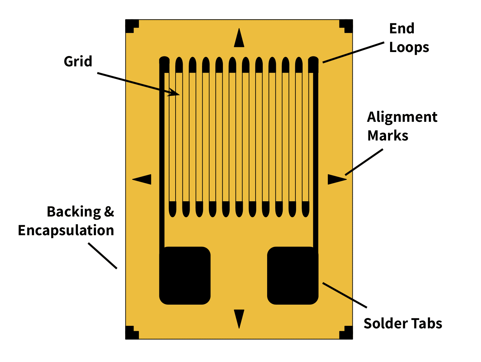
A bonded strain gauge consists of a thin wire etched in a back-and-forth pattern onto a non-conductive substrate material with connectors at each end of the wire (Figure 1). The length of the wire is the total length of all the loops; the end loops are wider to make negligible any difference in resistance from the same length of straight wire. Additionally, note the alignment marks indicating the direction of a normal (orthogonal) strain and an axial one. These are the arrowhead marks on the top and bottom (axial strain) and sides (orthogonal).
How Does It Work?
From a circuit standpoint, the wire acts as a resistor. The resistance is a function of the elastic properties of the wire. When the wire stretches, its length increases, its cross section decreases, and therefore its resistance goes up. When the wire is compressed, the opposite occurs. An analogy of this is flexible tubing. When stretched, it lengthens and narrows in cross-section which restricts the fluid flow compared to the original tube.
The ratio of the wire’s change in length divided by the wire’s original length is known as its mechanical strain. It is expressed as the equation: $$\epsilon = \frac{\Delta{L}}{L} $$
where \(\epsilon\) is the conventional symbol for strain, \(\Delta{L}\) is the change in length of the wire and \(L\) is the original length of the wire.
The relationship between the change in resistance of the strain gauge, and the strain in the etched wire due to an applied load, is approximately linear within the elastic limit of the wire. This relationship is expressed as a ratio known as the gauge factor (\(G\)). That is: $$G=\frac{ \frac{\Delta{R}}{R}}{ \frac{\Delta{L}}{L}}$$ $$or$$ $$G=\frac{ \frac{\Delta{R}}{R}}{ \epsilon} .$$
This linear relationship is the key to the strain gauge’s operation. The applied load creates a strain which in turn alters the resistance. Consequently, a voltage drop through the strain gauge will change depending on whether the gauge experiences a load or not. This change in voltage due to a change in applied strain produces a corresponding change in the strain gauge load cell’s output voltage.
What About Unbonded Strain Gauges?
Unbonded strain gauges also exist but the bonded type are most common and therefore this article focuses on the latter.
What is a Strain Gauge Load Cell?
A strain gauge load cell is a force transducer that uses the strain gauge technology described above. Within the load cell, the strain gauge is bonded to, or micromachined onto a non-conducting substrate layer. Together, the conductor and substrate form a flexible component. This component is then bonded to an elastic structural element, typically a metal forged into a specialized shape.
What Shapes Do Load Cell Structural Elements Have, and Why?
Strain gauge load cell structural element shapes can be beams, s-beams, or disk-like, to name a few. Why are there different shapes? Because this shape determines how the structural element can bear a load; different shape broaden the possible measurement applications. See Choosing the Right Load Cell For Your Job for an in-depth description of load cell structures and their applications.
What Is the Importance of the Strain Gauge Orientation Within the Load Cell?
Within the load cell, the location of the strain gauge corresponds to the point in the structural element that experiences the most strain when it bears a load. The gauge orientation is typically such that its long length lies along the principal axis of the measured force. Accurate readings from these devices depend on the applied force being completely axial to the intended force direction.
Gauges oriented along different axes exist to eliminate unwanted forces or measure other forces such as torsion. That is, just as the shape of the structural element depends on the load it will bear, the number of strain gauges and their location depends on the requirements of the system to cancel unwanted strains, temperature effects, and similar issues. The next section explains this in more depth.
Strain Gauge Load Cell Circuitry
Strain gauges have load limits. The strain on the wire cannot exceed the point where the metal will no longer return to its original length but instead permanently deforms. For most metals, this change is very small. For example, for steel the elastic limit occurs at a strain of 0.001 mm/mm.
The gauge factor tells us the resistance change in a metal is proportional to the strain. For most metals, the gauge factor is around the order of 2. This means for a strain gauge of 100 ohms unloaded, assuming the strain at the elastic limit is 0.001, the maximum change in resistance possible within the elastic limit is about 0.2 ohms.
Obviously this resistance change is very small. In fact, if a simple ohm-meter were to measure it, the change in resistance in the strain gauge would be so small that it would fall within the percent error of the meter, and therefore would be imperceptible. To accurately measure this resistance change, a strain gauge load cell employs a simple circuit known as a Wheatstone Bridge.
What Is a Wheatstone Bridge?
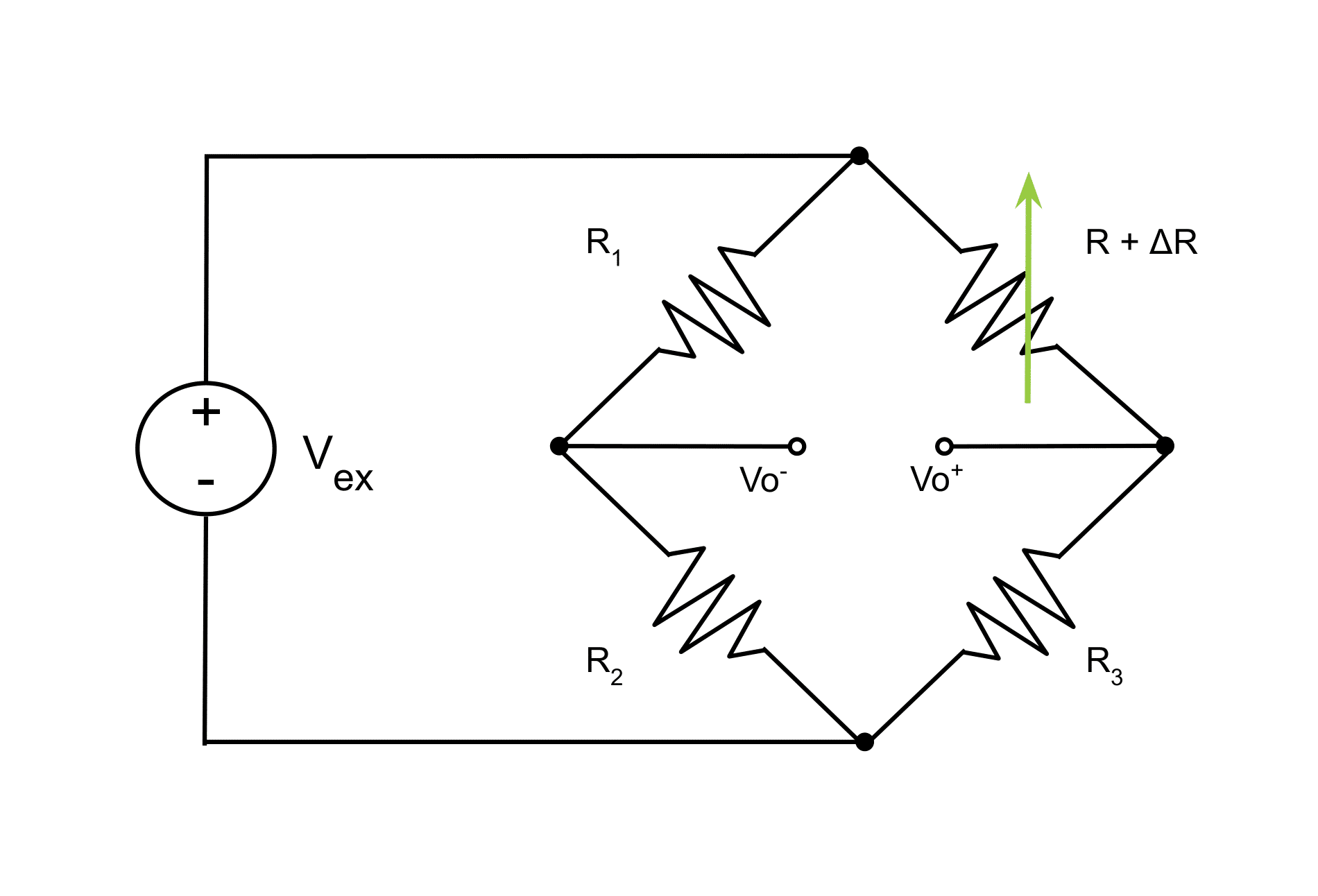
A Wheatstone bridge is simply two voltage dividers wired in parallel arms of a circuit with a common voltage source. Figure 2 shows a representation of this circuit.
The Input Voltage and Zero Load
The input voltage, \(V_{ex}\), is the excitation voltage. The variable resistor at \(R + \Delta{R}\) represents the strain gauge. \(R\), \(R_1\), \(R_2\), and \(R_3\) have equal resistances and \(\Delta{R}\) has a value of zero under no load. Therefore when the strain gauge bears no load, the voltages at the nodes \(V_{o-}\) and \(V_{o+}\) are equivalent. This means the output of the bridge circuit, which is the voltage difference across these two nodes, is zero volts.
The Output Voltage When the Gauge Experiences a Load
What happens when an applied force or load makes \(\Delta{R}\) non-zero? Let’s look at the general equation for the voltage at each output node. Recall ohm’s law states that the voltage between two nodes in a series circuit is equal to the current through it multiplied by the total resistance in that path, or more commonly seen as \(V=IR\). Rearranging, \(I = \frac{V}{R}\), the current on the left half of the bridge circuit in Figure 2 is then equal to \(\frac{V_{ex}}{(R_1 + R_2)}\). The two resistors along this path divide the excitation voltage at \(V_{o-}\). Substituting our expression for current in the left path for \(I\) in the ohm’s law equation, this voltage at the \(V_{o-}\) node is: $$ V_{o-} = V_{ex}\frac{R_2}{R_1 + R_2} $$
Similarly, the voltage at the \(V_{o+}\) node is: $$V_{o+} = V_{ex}\frac{R + \Delta{R}}{R + \Delta{R} + R_3} $$
The total output voltage is simply the difference between these two: $$ V_o = V_{o+} – V_{o-}$$ $$ V_o = V_{ex}\frac{(R + \Delta{R})}{(R + \Delta{R}) + R_3} – V_{ex}\frac {R_2}{R_1 + R_2}$$ $$V_o = V_{ex}\frac{(R + \Delta{R})R_1 – R_2R_3}{(R + \Delta{R} + R_3)(R_1 + R_2)} $$
Why Have a Bridge Circuit?
The reason this setup improves accuracy is that now the voltage drop across the strain gauge is being compared to the voltage drop across a similar resistance for the same excitation voltage, instead of being compared to the much larger excitation voltage itself. That means the change in voltage across the strain gauge will be the same order of magnitude as the comparison voltage; any error in output voltage will be a fraction of this. Also, any changes in strain due to temperature or other environmental factors will affect all of the resistors in the circuit equally. This becomes important in mitigating the effect of these environmental factors on the output.
It is important to note that, from the equations, it would seem that the larger the \(V_{ex}\), the larger the output signal; this may seem advantageous for displays or to produce a higher signal-to-noise ratio. However there are limits to excitation voltages for signal quality. See “Does Load Cell Excitation Voltage Matter” in our FAQ.
The Quarter, Half, and Full-Bridge Configurations
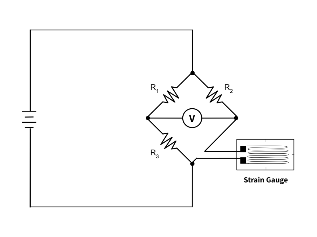
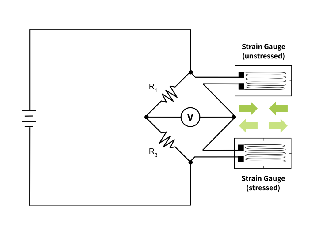
All Wheatstone bridges have four resistive elements. However in load cell design, the number of those elements that are strain gauges vs non-variable resistors is flexible. If only one of the resistive elements in the bridge is a strain gauge, it is a quarter bridge. If two are strain gauges, it is a half bridge. And in the case where all four resistive elements are strain gauges, the Wheatstone bridge is a full bridge. See Figures 3-5 below.
How Does the Bridge Configuration Affect Load Measurement?
The pros and cons of each bridge configuration motivate the choice for a particular application. In general, fewer gauges mean cheaper construction and easier installation. However, additional gauges increase bridge output, allow for temperature compensation, and cancel unwanted strain components.
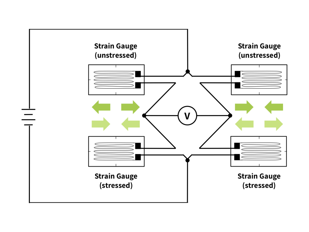
Cancelling Unwanted Strain Components
To describe an example, one must know the property of the Wheatstone Bridge that strains on adjacent positions in the bridge cancel, while strains on opposite bridge arms sum. Now let’s assume that we want to cancel a bending strain in a loaded beam and just measure any tensile strain. To accomplish this, the structural element contains a strain gauge at both the top and the bottom (vertically aligned); the circuitry in the load cell is a half bridge configuration with the gauges on opposite bridge arms. The strain measured at the top gauge will have the load strain plus tensile strain due to bending; the bottom gauge will have a compressive bending component similar in magnitude but opposite to the tensile component at the top. The bridge output will be the sum of the common strain components but the opposite strains will cancel to 0V.
Cancelling Unwanted Temperature Components and Measuring Non-Axial Forces
Likewise, strain components due to temperature add equally to all gauges in a bridge configuration; therefore, by placing a non-loaded gauge in a position adjacent to a load-bearing one, the strain components due to temperature will cancel.
In addition, bonding gauges at angles to each other on a measuring device can account for additional (non-axial) strain components and determine the angle of maximum strain. This configuration of strain gauges is called a strain gauge rosette.
Conclusion
This article introduces the underlying principles of a strain gauge, the main component in Tacuna Systems’ load cell product line. Strain gauges have many advantages in load cell construction. These include low cost, high accuracy (especially due to the wide variety of bridge configurations and bonding geometries) and durability. Because they can fit into a wide array of supporting structures and can handle a broad range of loads, strain gauge type load cells are practical for many applications. They are truly versatile.
The article, Choosing the Right Load Cell For Your Job, complements this one. It describes the different strain gauge load cell types offered by Tacuna Systems, and their uses. Also, see Why Do I Need a Load Cell Amplifier (and Other Signal Conditioners)? and Load Cell Summing: Junction Boxes, Signal Trim, and Excitation Trim for further information on load cell signaling.