Choosing the Right Load Cell for Your Job

You would not buy a sports car if you planned on towing a trailer, the same way you wouldn’t rent an excavator to dig a fence post-hole. The key to starting any job is having the right tools and equipment. This is especially true for load cell and force measurement applications. The right load cell is critical to obtaining high-quality, accurate readings. But how do you choose the right one?
Fortunately, industrial load cell designs accommodate many different tasks, sizes, orientations, durability, environmental factors, and signal outputs. The key is to find the right match from this wide variety, taking into account all of these criteria simultaneously. This article first reviews the purpose and features of each load cell design category and then makes high-level recommendations for how to choose a load cell based on those strengths. (See this table at the end of this article for a quick summary.) For specific project recommendations, Tacuna Systems offers complementary design guidance (like that which we gave to the researchers in this interesting featured customer project).
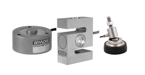
Note this article focuses specifically on strain gauge load cells.
1) Consider the Load Input Direction
A load cell is a sensor device that converts the energy of an applied force into a quantifiable electrical signal. The strength of the signal is proportional to that force — compression, tension, pressure, etc. Therefore an accurate reading requires the vector components of the force to align completely with the direction of force the load cell is designed to measure.
In a perfect world under ideal conditions, measurement device operators would control the orientation of an applied load and the method for applying it. Because there is no perfect approach, different types of load cells exist to compensate for irregularities and the uncontrollable factors in load measuring.
Also when designing a load cell, engineers consider the physical principle of materials called stress. Stress describes the intensity of the internal forces acting on a specific section of an object subjected to an applied load. If you bolt a steel I-beam to a wall and hang 500 lbs from its free end, you could examine individual ‘slices’ of this beam and see that the loading position affects each one differently.
Knowing the type of stress a physical system undergoes and the orientation of the load influences the design of the various load cells described in this article, and which to choose for a project.
Normal Stress and Normal Loading
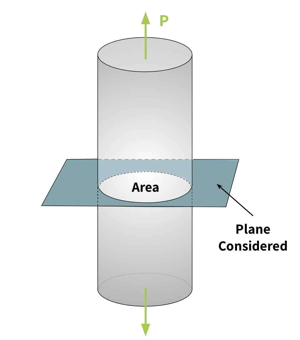
A normal load is a force whose direction is exactly perpendicular to a defined plane or surface it acts upon. Normal stress is stress due to that force. This is the simplest type of stress (“\(\sigma\)” in equations) to calculate since it is based only on the force applied (\(P\)) and the cross-sectional area (\(A\)) affected by the force. That is,
\( \sigma = \frac{P}{A} \)
Normal stress can be either tensile or compressive. Tensile forces pull or stretch the body, while compressive forces squeeze the body.
An example of a measurement system for normal loads is a grocery or postage scale, where the object weighs directly down on the plate of the scale. that is, the load direction is exactly perpendicular to the scale plate.
It is important to note that normal stress differs from normal loading. Load cells designed for normal loading do not always experience normal stresses. They also can undergo shear stress and bending as described below.
Bending
Bending is when an external force or moment applied to a structural element causes it to bend. An object’s reaction to this external force differs from its reaction to a normal load. Half of the element sees tensile normal stress, while half of it sees compressive normal stresses. See Figure 3.
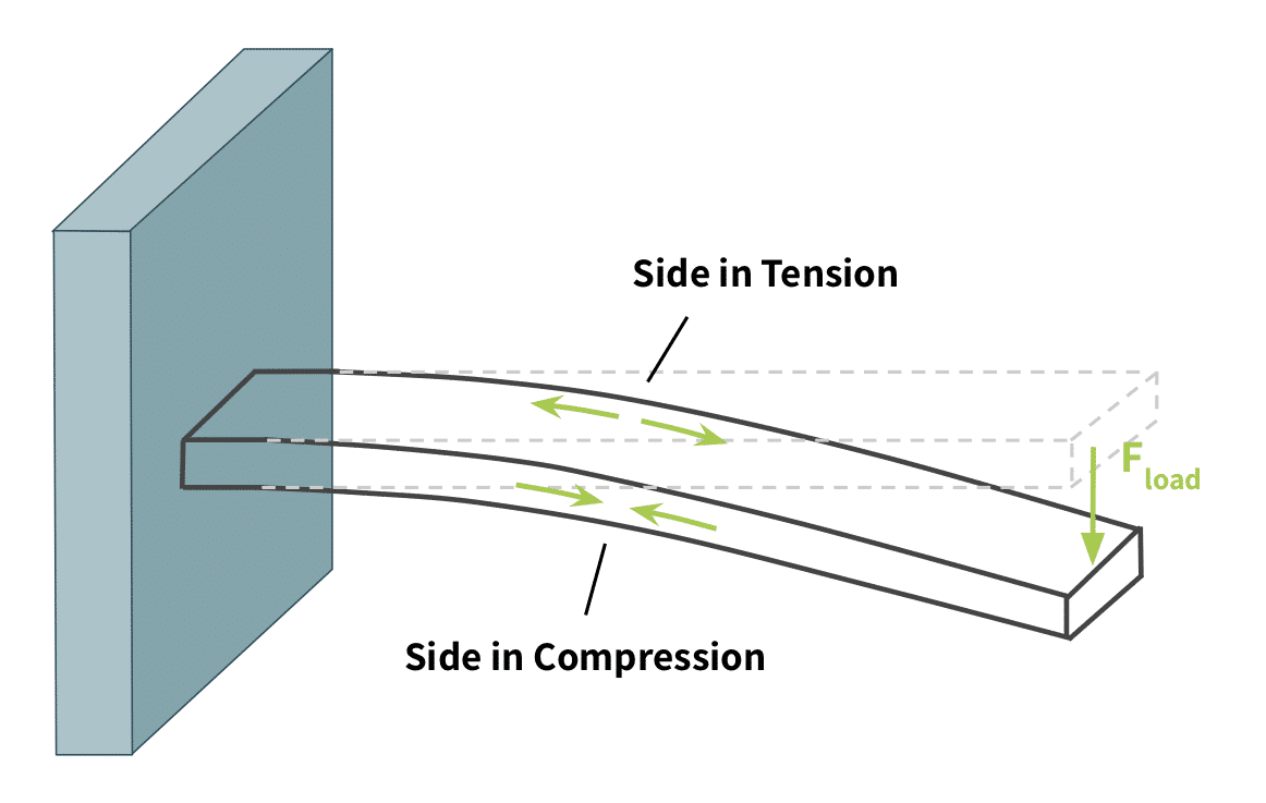
The difference between tensile and compressive stresses is important in selecting load cells because not every transducer is capable of reading both. Moreover this difference is an important consideration for structural components within a project since the failure modes of tension and compression are different.
Shear Stress
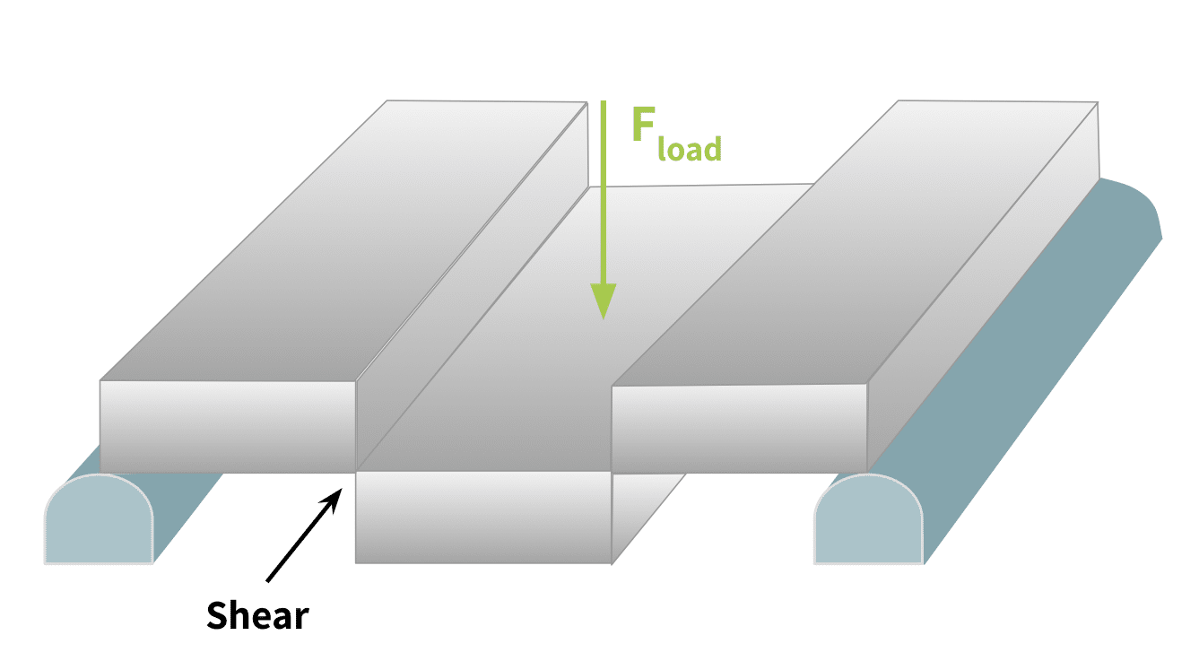
Shear stress is a stress component that acts in the considered plane, much like a sheet of paper between two opposing blades of scissors. The point of maximum shear is where the opposing blades meet and cause the paper to shear into two parts. Figure 4 below labels the shear force created by the normal load \(F_{load}\) and models the deformation in the structure created by it.
Torsion
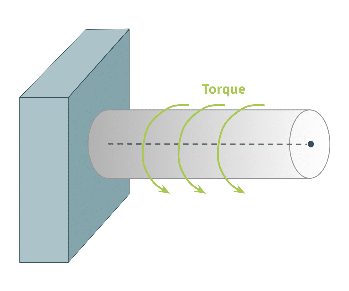
Torsion occurs when an applied external force (or “torque”) causes the structural body to twist. It is a very important stress component to consider because all rotating or spinning objects experience it. This includes wheel axles, driveshafts, gears, motors, propellers, etc. The figure below illustrates this force. To clarify, torque is the force that causes the stress component of torsion.
2) Consider the Object to be Weighed: Capacity, Resolution, Shape
This may seem obvious, but the weighed object determines both the divisions required of the load cell, or its resolution, and the rated capacity of the load cell. These determine the desired load cell class. That is, not only is the minimum and maximum weight of the object important, but the desired resolution or smallest weight difference that must be measured. (For more details on this point, see the article, What Is the Lowest Weight a Load Cell Can Measure?) Again, remember that the maximum capacity must account for the maximum possible axial weight components that environmental factors could add. (See “Vibration and Wind” below.)
Likewise, the weighed object, along with the type of applied forces (as Section 1 describes), determine the actual geometry of the load cell. Load cells in platform scales are of very different shape than those deployed in cranes. Choose a load cell whose shape, mounting, and capacities accommodate the shape, maximum and minimum weights, and smallest weight variances of the measured object.
3) Consider the Environment the Load Cell Will Operate In
Many environmental factors affect the operation of a load cell, and therefore how to choose one. This section explains those factors that affect the choice of material of the load cell body or its type of IP or weight capacity rating.
Moisture
One of the most damaging environmental conditions for a load cell is moisture intrusion. Moisture can cause corrosion to the load cell material, short circuits in its electronics, and other failures. However load cells often operate in environments where moisture is a given, whether they be outdoors or in areas such as food preparation environments where equipment must be cleaned to maintain sanitary standards.
Chemical Exposure
Like moisture intrusion, chemical exposure can cause corrosion to the load cell material and similar failures. This factor requires special consideration in environments such as food preparation or medical environments where equipment must be cleaned to maintain sanitary standards, or any industrial application where chemical exposure is a given.
Temperature
Temperature can make a tremendous difference in the operation of a strain gauge load cell, since the load cell employs resistive elements and temperature affects electrical resistance. A system designer must ensure that the chosen load cell can function accurately within the temperature extremes the load cell will be exposed to. Likewise the load cell itself and other system components must compensate for any variations due to temperature.
Vibration and Wind
Vibrations such as from seismic activity, heavy traffic, or industrial activity can artificially add loads to a load cell. Likewise, lateral forces due to wind can add force vectors that are axial to the intended load direction of a load cell. Proper installation can mitigate much of the effect of these conditions. However, the choice of load cell capacity should take into account any artificially added load that could occur due to vibration or wind. That is, the load cell’s rated capacity should be high enough that the maximum load plus any potential added environmental loads do not exceed this limit.
4) Consider the Desired Accuracy, Error Ratings, and Ease of Calibration
Finally, once the shape, material, IP rating, and load cell class are understood, the designer of a measuring system must consider factors such as the combined error, hysteresis, creep, non-linearity, and repeatability ratings listed on the load cell data sheet. These must fall within the measuring system’s requirements.
All load cells require maintenance and periodic calibration to stay within these error specifications with repeated use. The load cell’s quality will affect not only its durability but how easily it maintains calibration; the system design will determine how easily a field calibration may be performed. In this case, the reliability of the load cell’s vendor to provide calibration service and support is extremely important as well.
Load cell class ratings and other load cell approval markings can provide a quick understanding of a load cell’s specifications. The following articles explain these approvals further: Load Cell Classes: NIST Requirements, Load Cell Classes: OIML Requirements, and Measurement System Compliance Certificates and Approvals Explained.
Choose a load cell that meets the accuracy requirements of the measuring system and has both quality construction and vendor support to maintain its calibration. The article, How Can I Tell If a Load cell Is a Quality One? answers this important question.
5) Select the Load Cell Type for the Application
Now that we understand the main forces creating stress on an object (normal, bending and shear, and torque) and the other factors determining the selection of a load cell, we can match some load cell types to their optimal application. Below are a few types of load cell transducers and the applications where they best perform.
Load Cells for Normal Loading
Any scale where the object is placed on top of a platform will bear a normal load. The weight of the object is a force that acts vertically downward, causing the load cell to react. The load cell will respond with an output signal proportional to the weight of the object applied. This section describes a few load cell types in the Tacuna Systems offering.
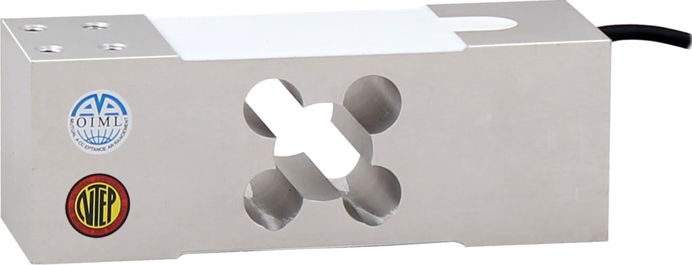
Single Point or Platform
Single point load cells are most commonly used in low capacity, compact weighing, such as balances, food scales, pricing scales, packaging scales, medical and pharmaceutical scales, on-board weighing, and other retail applications.
These load cells accept loads that are not perfectly centered on a weighing platform. Each single point load cell has a designated loading area to apply the force. This prevents the need for load cell trimming, making these devices ideal for single load cell applications. Load cell trimming combines measurement signals from various load cell devices through a summing box when a measuring system consists of multiple load cells; this ensures that a measurement from a scale is the same regardless of the placement of an object on the loading platform.
The Tacuna Systems product line of single point load cells ranges in capacities from 300g to 2000kg.
For a look at innovative uses for these types of load cells, see these articles in our “Featured Customer Projects” section of our Knowledge Base: Load Cell Research Example: Hydrodynamic Characteristics of Freshwater Snails, Measuring Contact Forces on Soft Materials for Medical Robotics and Other Applications, and Bearing the Load of Social Responsibility.
Canister and Disk Load Cells
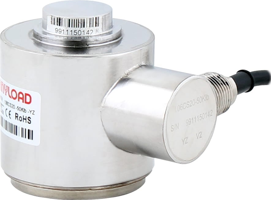
Canister or disk load cells are a type of load cell used specifically for compression loads. The load passes through the top of the “button” of the device. Strain gauges at the internal core of the load cell measure compressive normal loads.
Canister load cells are designed to handle much heavier loads but are much bulkier than other compression load cells. Tacuna Systems products’ capacity ratings range from 25 to 500,000 kg. The sturdy design is resistant to bending loads and side loads, making these devices ideal for systems with several directional load components where only one must be quantified.
Miniature Load Buttons
Miniature load button load cells are a type of small canister load cell for lighter capacities, between 5 to 45 lbs.
They commonly appear in small retail and postal scales. Like other canister load cells, miniature load button load cells can be used in systems where forces exert from different directions but measuring only one of these directional force components is necessary. You can read about interesting research examples that used these types of load cells in Load Cells in Education: Neuromuscular Aspects of Human Movement Force Measurement, and Measuring Contact Forces on Soft Materials for Medical Robotics and Other Applications.
Planar Beam
Planar beam load cells are chosen specifically for their low profile. They frequently appear at the four corners of a scale, trimmed together through a junction box that combines their measurement signals.
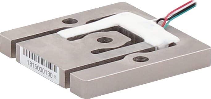
Planar beam load cells work well in applications where goods or products are sold commercially by weight. These commercial applications require scales that are “legal-for-trade” or “trade-approved.” Examples include airport luggage scales and grocery scales.
Planar beam load cells typically weigh loads in the 10-400lb range. The lowest capacity in the Tacuna Systems product line is 3.75Kg and the highest is a 375Kg load cell.
S-Beam Load Cells
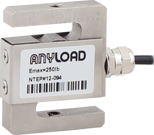
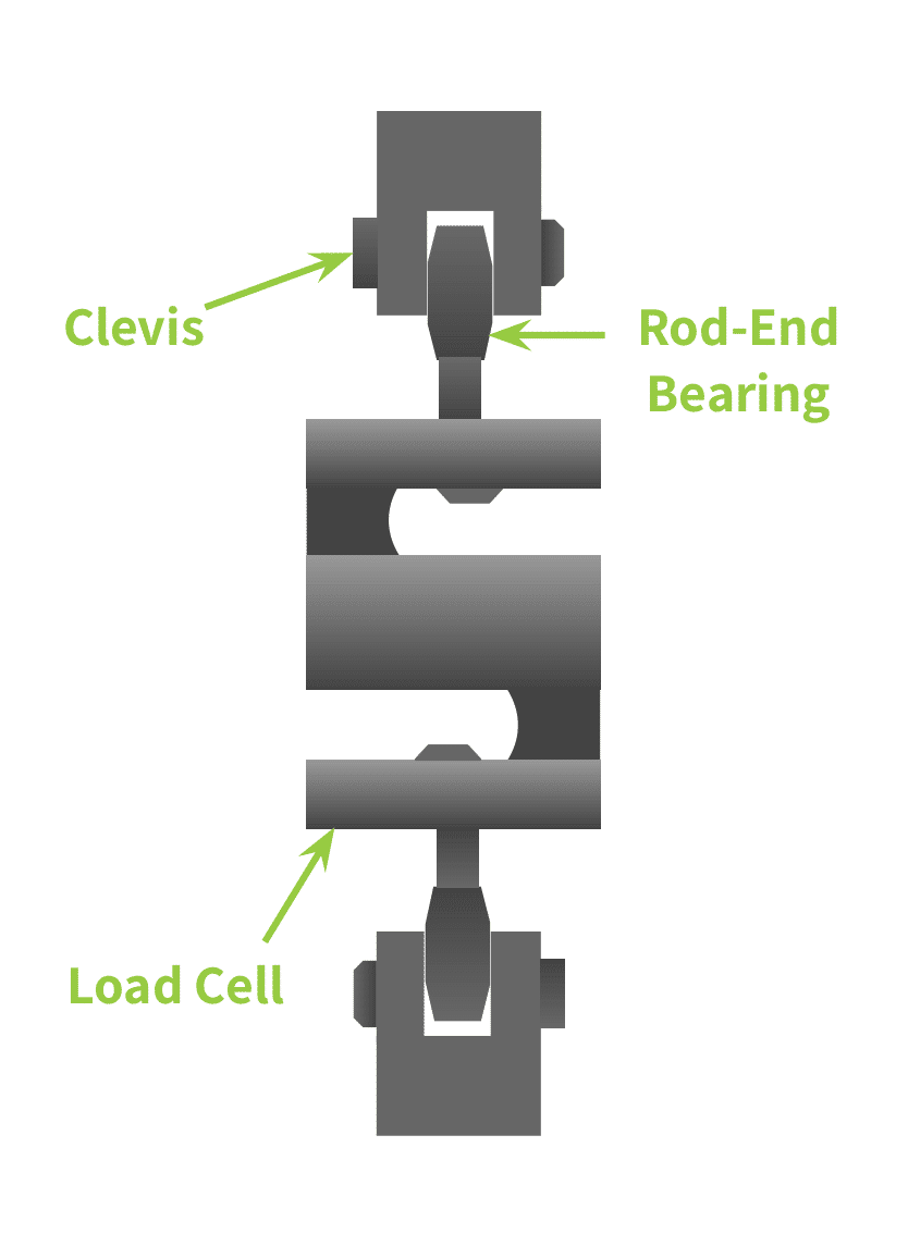
S-beam load cells are powerful because they can be used in both tension and compression. They are durable with high endurance. This makes them ideal for light performance testing such as testing the resistance of doors, hinges, or springs. Their versatility is obvious when you consider the number and diversity of research examples in our “Featured Customer Projects” section of our Knowledge Base that use them. See Cal Poly Rocketry Test Stand Gets off the Ground with Tacuna Systems, Research With Load Cells: Effects of Military Load Carriage on Ground Reaction Forces, Load Cells in Education: Neuromuscular Aspects of Human Movement Force Measurement, and Next-Gen Transmissions for High-Performance Hybrid Cars.
These load cells are, however, susceptible to large bending moments due to their geometry. Rod-end bearings and clevises help orient the load path in the desired direction.
Tacuna System’s offering of S-type load cells range from a rated capacity of as low as 2Kg to 40,000Kg.
Load Pins
Load pins are designed for suspended systems where a pin supports the structure. They can be used in shackles with clevis pins, sprockets, or pulleys. When in use, the load pin experiences shear forces. Strain gauges in a bore through the center of the pin measure these forces.
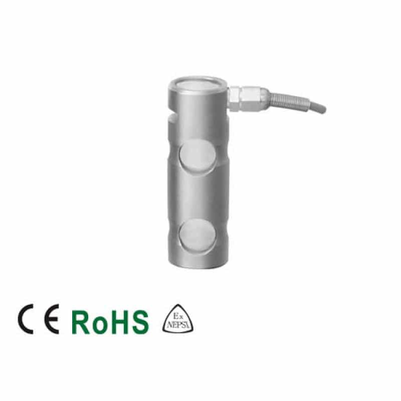
Load pins generally have a capacity of up to 100 tons and can handle both tensile and compressive loads. This makes them ideal for large-load applications. Their design is specific to systems needing real-time measurements where a support pin is part of the structure. That is, this load cell type replaces the usual pin as a structural element. In compression applications, the pin replaces a bolt that supports the load.
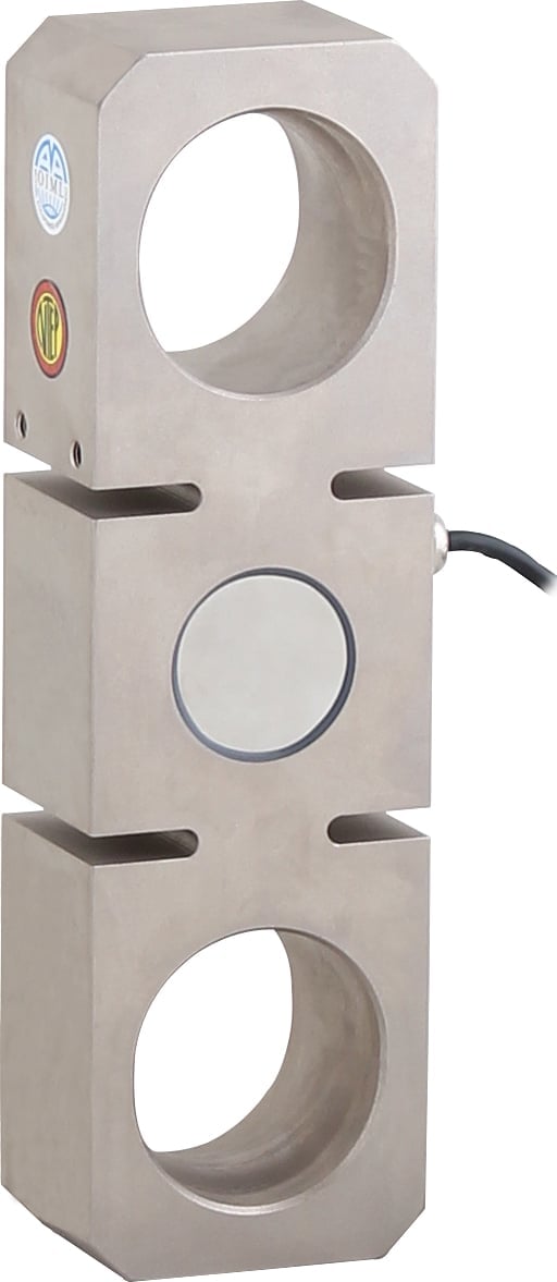
Tension Link
Tension link load cells are similar to canister load cells but are for suspension applications. Like canister load cells they handle much heavier loads, but are much bulkier than other types. They are designed for crane scales or cable strength tests for loads up to 100 tons.
Tension link load cells typically operate in areas with a wide variety of environmental exposure including construction sites and ports. For this reason they have environmental protections within their design that allow them to withstand heavy amounts of humidity, salt from seawater, and high coastal winds. Their design also makes them resistant to bending loads, side loads, and torsion.
Bending and Shear Force Load Cells
Shear beam load cells are designed to take loads that cause shear stresses or bending moments. The alignment of the load path through shear beam load cells should be vertical. These devices do not compensate well for torsion or other significant side loads out of plane with the loading path. Proper mounting can help mitigate misalignment. For more information on load cell mounts, see A Comparison of Tacuna Systems Load Cell Mounts.
Single-Ended Shear Beam
Single-ended shear beams are a simple and affordable load cell option for medium capacities (2 – 2650 lb). One end of the beam is fixed while a load is applied to the free end, as Figure 15 below shows.
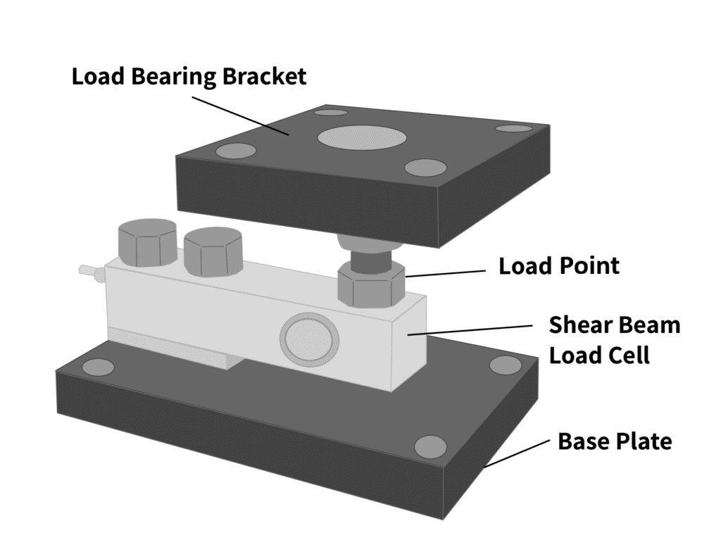
The shear beam deforms under an applied force, allowing the strain gauges to equate a load based on the amount of bending it experiences. These load cells are ideal when there is a narrow physical space between the load cell and its mount or fixture. Single-ended shear beam load cells are also practical for large weighing applications where multiple load cells combine to form a single measurement system. Examples of these applications include tanks, hoppers, and other vessels.
Again, our customers have come up with some interesting uses for this type of load cell. See Load Cell Research Example: Hydrodynamic Characteristics of Freshwater Snails for one such example.
Double-Ended Shear Beam
Double-ended shear beam load cells function similarly to single ended. However, double-ended beams are fixed at both ends and the load is applied to the midway point.

Double-ended shear beams have higher load capacity ratings than single-end, so when supporting greater loads with size constraints, implement double-ended load cells. These devices often appear in industrial weighing applications such as floor-scales, weighing tanks, and other vessels. Tacuna Systems offers double-ended shear beam load cells rated from 1000-400,000 lbs.
Torque Transducers
These transducers, like other load cell transducers, convert mechanical inputs into a quantifiable electrical signal. Torque cells specifically detect torsional input. In other words, they detect forces that causes the body to twist.
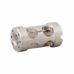
Most torque transducers use full or half Wheatstone bridge strain-gauge configurations. The gauges typically measure the applied loads causing shear strain and bending strain and combine these outputs to quantify torsion or torque.
The two main types of torque transducers are static and rotating.
Static Torque Transducers
Static devices are used when one end of the shaft or measured body is fixed to a non-moving frame. Creating them is simple and easy to accomplish with conventional strain gauges and wiring.
Rotating Torque Transducers
Rotating parts, like driveshafts or propeller masts, are more difficult to measure due to their rotation. Connecting wires to a rotating object creates a need for engineering solutions like slip-rings or wireless transmission.
6) Summary
The table below summarizes the features of the strain gauge load cell categories sold by Tacuna Systems, and which load cell to choose for a general application. For guidance on which material to choose for a type of load cell, see this FAQ answer.
Summary of Load Cell Types and Their Application
| Type | Material | IP Rating | Application |
|---|---|---|---|
| Disk/Canister | Aluminum, Alloy Steel, Stainless Steel | IP66, IP67, IP68 | Heavy compression loads |
| Double-Ended Shear Beam | Aluminum, Alloy Steel, Stainless Steel, Tool Steel | IP66, IP67, IP69 | Floor scales and heavy-duty weighing scales for trucks, vessels and tanks |
| Load Pin | Stainless Steel | IP67 | Industrial, aeronautical and marine environments |
| Miniature | Aluminum, Stainless Steel | IP66, IP67 | Industry computerization, automation, cable testing, pneumatic and hydraulic controls |
| Planar Beam | Aluminum, Alloy Steel | IP65 | Postal scales, retail checkout scales, medical equipment, airport baggage scales |
| Single Point | Aluminum, Alloy Steel, Stainless Steel | IP66, IP67 | Industrial scales, filling and packaging systems, on-board weighing systems, medical equipment |
| Single-Ended Shear Beam | Aluminum, Alloy Steel, Stainless Steel | IP65, IP66, IP67, IP68 | Industrial floor scales, barrel scales, low to medium capacity vessel weighing |
| S-Type, S-Beam | Aluminum, Alloy Steel, Stainless Steel | IP65, IP67, IP68 | Automotive components, polymer strain testing, industrial food processing |
| Tension Link | Alloy Steel, Stainless Steel | IP65, IP67, IP68, IP69K | Cable and towing tension, crane and hoist scales, tensile verification systems |
References
- Mechanics of Materials, 9th edition, Russell C. Hibbeler
- Measurement and Instrumentation in Engineering: Principles and Basic Laboratory Experiments, 1st Edition, Francis S. Tse, Ivan E. Morse
- ISO 7500-1, Metalic Materials – Verification of Static Uniaxial Testing Machines – Part 1: Tension/Compression Testing Machines – Verification and Calibration of Force-Measuring System, 3rd Ed, 2004-08-15
- OIML R 60-1, Metrological regulation for load cells Part 1: Metrological and technical requirements, Organisation Internationale de Métrologie Légale, Edition 2017
- NIST Handbook 44, Specifications, Tolerances, and Other Technical Requirements for Weighing and Measuring Devices, as adopted by the 104th National Conference on Weights and Measures, 2019, National Institute of Standards and Technology, US Department of Commerce

