
Force shunts occur when structural supports, piping, or safety restraints divert applied loads away from a primary sensor’s measurement axis. Often, structures or mounting techniques can mitigate this effect. However, when these mechanical bypasses are unavoidable, accurately quantifying shunted forces is essential to accurate weighing. Here, we explore the options.
Key Takeaways
- Force Shunt Mechanism: Secondary load paths (check rods, piping, expansion joints) divert a portion of the process load away from the primary load cell, introducing systematic measurement error.
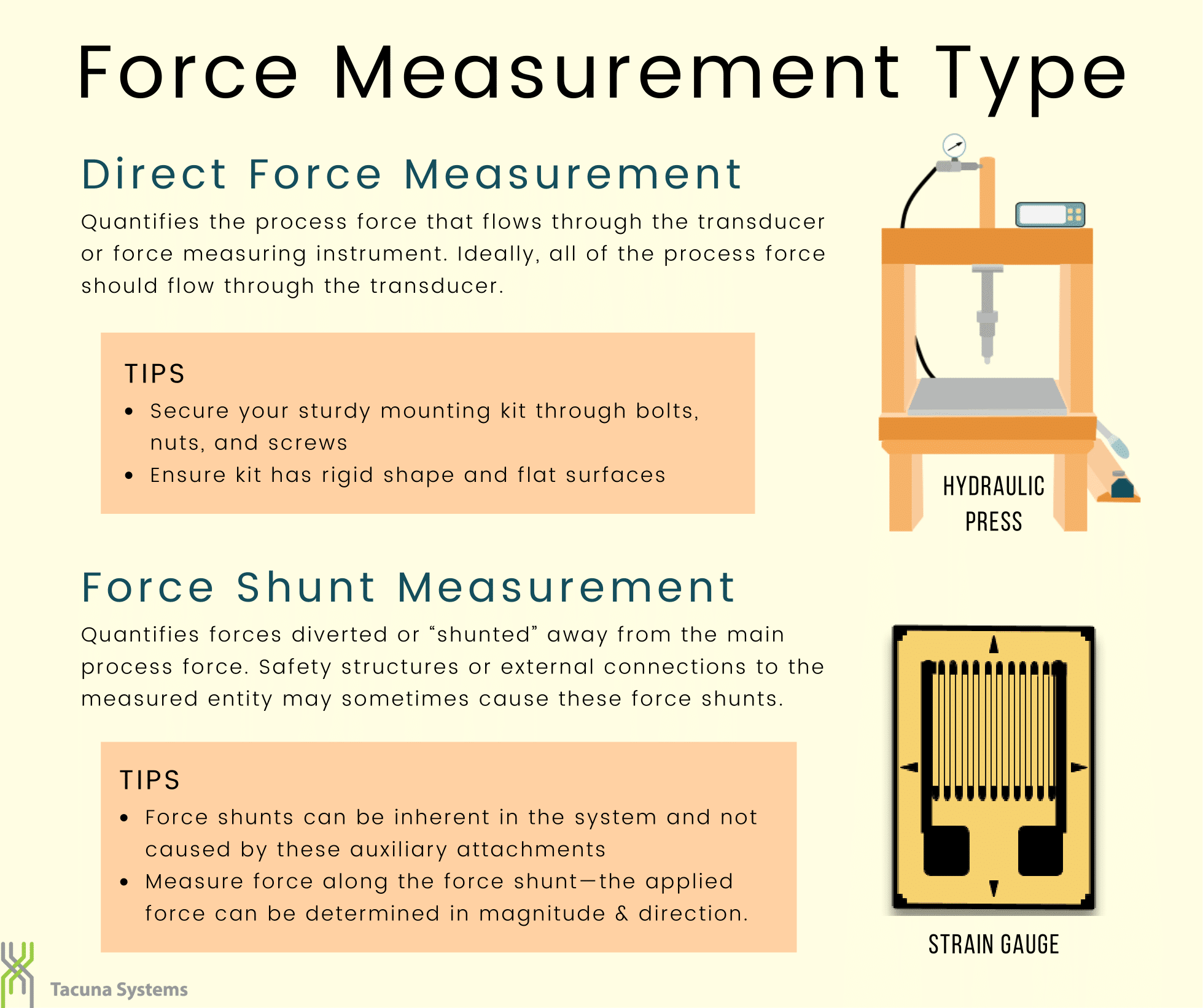
- Direct vs. Shunted Measurement: Direct force measurement channels 100% of the load through a sensor flexure; force shunt measurement measures the fraction of force passing through a parallel structural path.
- Sensor Selection: Surface-bonded strain gauges avoid altering the stiffness of delicate assemblies. Strain gauge load cells provide built-in environmental sealing and faster mechanical installation. Multi-axis load cells quantify the primary axial load (\(F_x\)) and the shunted side loads (\(F_y, F_z\)) at a single mechanical junction with a single device.
- In-Situ Field Calibration: Systems with inherent force shunts must always be calibrated in place after final assembly to zero out static shunt resistance and establish true load-to-output ratios.
What is a Force Shunt and Why Does it Matter?
In electrical engineering, a shunt provides a low-resistance parallel path that diverts electric current. Similarly, a force shunt is a secondary mechanical structure that diverts a portion of the main process load through a parallel, low-resistance force path.
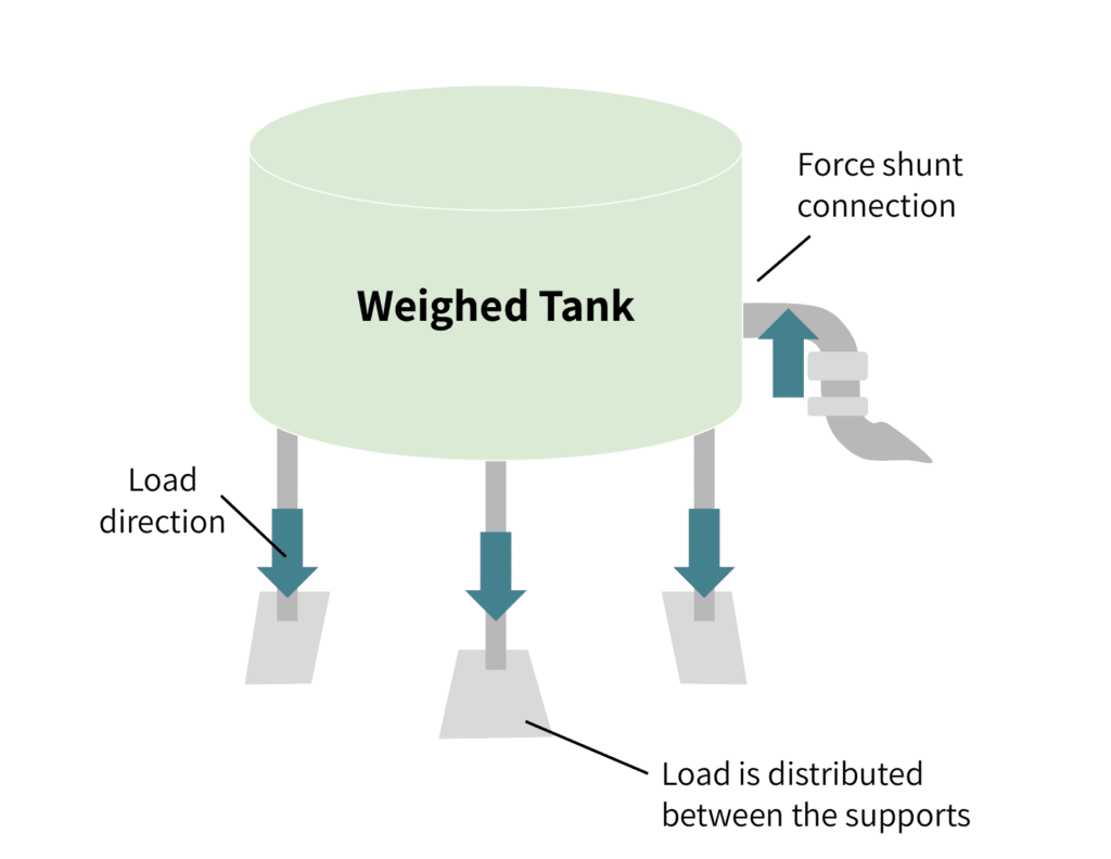
Common structural force shunts include:
- Mechanical check rods and stay rods
- Safety restraint chains and bumper stops
- Rigid process piping and conduit connections
- Vessel thermal expansion guides
While an electrical shunt typically diverts the majority of current, a mechanical force shunt usually absorbs only a fraction of the total force. Nonetheless, unmeasured force shunts do degrade overall system accuracy and risk structural overload if safety supports fail.
That is, measuring these diverted forces not only quantifies them. It also provides a means to predict and circumvent support structure failures.
In an ideal weighing assembly, rigid mounting hardware isolates forces, channeling 100% of the load along the sensor’s primary axial path. However, when secondary mechanical structures like piping, check rods, or thermal expansion guides unavoidably divert forces away from this primary axis, engineers must deploy specialized sensors along the path of the diverted loads. Here, we look at three common methods.
Force Shunt Measurement Methods
The three primary methods for measuring forces diverted through a parallel structural path are the use of surface-bonded strain gauges, single axis load cells, and multi-axis load cells. Engineers will make their selection depending on structural stiffness, space constraints, and force directionality.
1. Surface-Bonded Strain Gauges:
With this method, bonded foil strain gauges attach directly to the structural member creating the force shunt (such as a pipe, leg, or check rod) using epoxy adhesive.
- Primary Benefit: Because the gauge has near-zero mass and stiffness, it does not alter the natural deflection or dynamic behavior of the host structure.
- Implementation: Full-bridge (or rosette configurations) isolate axial forces while canceling unwanted bending moments, torsion, and thermal expansion effects.
- Drawbacks: Bonded gauges are highly complex to install. They require manual surface preparation, lead wire soldering, protective field coatings, and mandatory in-situ calibration. Surface-bonded strain gauges are best suited for delicate or space-constrained assemblies.

2. Single-Axis Strain Gauge Transducers (Standard Load Cells):
This method uses standard strain gauge load cells. Their pre-bonded strain gauges are housed inside a sealed enclosure on a precision-machined internal flexure element.
- Primary Benefit: Their pre-mounted, pre-sealed gauges offer fast, reliable, and repeatable installation using standard mounting hardware. Intrusion protection can be as high as IP67/IP68 and they have built-in internal temperature compensation, making them suitable for harsh, outdoor environments.
- Implementation: Because a heavy structural support under a shunt load deflects very little, load cell flexures use localized “thinning” or flexure cutouts to concentrate strain directly beneath the internal gauges. See the engineering note below for further details.
- Drawbacks: Introduces additional stiffness to the parallel load path and measures force along a single predefined axis (\(F_x\) only).

Engineering note: The Mathematical Relationship Between Strain and Distance from Application Point
Strain gauge load cells are designed such that the area on the elastic element where the gauge is bonded (the load point) flexes more than the rest of the load cell body. This causes a mechanical strain on the elastic element, that varies with distance from the load point, according to the following relationship:
\begin{align*}
\varepsilon_ {SG}&=\frac{\varepsilon_{object}\cdot l_{sensor}}{l_{zone}}\\
\text{Where: } \ \
\varepsilon _{SG} &= \text{Mechanical strain present directly under the strain gauge}\\
\varepsilon _{object} &= \text{Average strain measured across the structural attachment (bolt) points}\\
l _{sensor} &= \text{Linear distance between the bolts/structural attachment points}\\
l _{zone} &= \text{Length of the localized, narrowed strain flexure zone}
\end{align*}
By adjusting the ratio between bolt spacing (\(l_{sensor}\)) and flexure zone length (\(l_{zone}\)), engineers can tune sensor sensitivity to match expected shunt force magnitudes.
3. Multi-Axis Strain Gauge Transducers (Vector Measurement):
When secondary structures divert forces off-axis in unpredictable or shifting directions, single-axis load cells miss the non-axial force components. A multi-axis load cell measures orthogonal force vectors (\(F_x, F_y, F_z\)) and moments (\(M_x, M_y, M_z\)) simultaneously at a single junction.
- Primary Benefit: These load cells quantify both the primary axial load vector (\(F_x\)) and the shunted side-load vectors (\(F_y, F_z\)) without requiring multiple single-axis sensors or complex mechanical linkages. They are best for applications with complex structural joints, piping connections subject to thermal twisting, or dynamic test frames where the direction of the force shunt changes during operation.
- Implementation: Placed at critical structural anchor points, piping flanges, or vessel tie-downs, they capture multi-directional forces caused by thermal expansion, piping stress, or dynamic structural sway.
- Drawbacks: These tend to have a higher sensor cost and they require multi-channel signal conditioning/DAQ hardware.
Force Shunt Measurement Methods Comparison Table
| Metric / Feature | Surface-Bonded Gauges | Single-Axis Transducers | Multi-Axis Transducers |
|---|---|---|---|
| Vector Capability | Single directional strain per gauge/rosette | Single force axis (\(F_x\) only) | Multi-directional (\(F_x, F_y, F_z\) & moments) |
| Shunt Quantification | Indirect (calculated via surface strain) | Indirect (requires known axis alignment) | Direct (measures axial and off-axis shunt vectors) |
Field Calibration in Force Shunt Systems
Factory calibration certificates reflect a load cell tested in isolation, assuming 100% of the applied force reaches the sensor. In a force shunt situation, surrounding structural members absorb a portion of that load based on their stiffness, rendering the factory calibration curve invalid for the assembled system. In-situ field calibration is mandatory after final mechanical assembly. The recommended checklist is as follows:
- Zero-Load Tare: Capture the baseline sensor output when the system is empty to zero out static dead load and structural piping bias.
- Full-Scale Span: Apply the maximum rated load using a certified reference force (calibration weights or a hydraulic calibration rig) directly along the primary load axis.
- Amplifier Adjustment: Adjust the gain on the signal conditioner or amplifier until the display output matches the known applied force.
- Environmental Control: Maintain steady ambient temperature and humidity during calibration to eliminate thermal drift artifacts.
Where force shunts are present, field calibration ensures that the measuring setup provides an accurate reading of the actual force shunt as opposed to other forces present. Choosing a quality load cell will improve both the reading’s reliability and the load cell calibration’s longevity despite repeated uses. See our guide, Calibrating the Force Measuring System, for a more complete understanding of field calibration.
Summary and Next Steps
Measuring force shunts allows engineers to evaluate structural safety bypasses and correct measurement errors in complex weighing systems. While surface-bonded strain gauges excel in lightweight or space-constrained assemblies, standard strain-gauge load cells offer superior environmental durability and rapid field deployment, and multi-axis load cells capture complex off-axis force vectors at a single junction.
Explore Tacuna Systems’ catalog of strain gauge load cells and signal conditioners, or contact our engineering team for assistance designing a custom force measurement setup.