
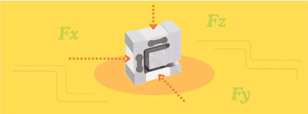
Load cells often form the basis of weigh systems where the load travels in a single, known direction, such as bench or crane scales. Yet plenty of applications exist where multidirectional forces are not only present, but desirable to quantify. In robotics, biomechanics, wind-tunnel testing, and structural fatigue work, the angled and torsional forces present are impossible for a standard load cell to capture because it can only “see” force along its one built-in axis. Multi-axis load cells solve this by measuring every force component independently, giving a full force-vector picture instead of a partial one.
Key Takeaways
- Full Vector Force Resolution: 3-axis (triaxial) load cells measure orthogonal forces (\(F_x, F_y, F_z\)), while 6-axis load cells add rotational moments (\(M_x, M_y, M_z\)) for complete 6-DOF force and torque profiling.
- Off-Axis Error Elimination: Single-axis sensors subject to multidirectional loads can suffer measurement errors caused by cosine angle shift, direct bridge coupling, and bending moments.
- Strain Gauge vs. Piezoelectric Sensor Selection: Strain-gauge multi-axis cells excel at static and quasi-static force tracking, whereas piezoelectric cells are designed for high-frequency dynamic transients.
- Channel Conditioning & Vector Decoupling: Each axis senses using an independent Wheatstone bridge that requires its own conditioned channel. Hardware crosstalk is decoupled mathematically using a calibrated \(3\times3\) or \(6\times6\) matrix applied to time-synchronized DAQ inputs.
- Per-Axis Capacity Sizing: Since capacities are often asymmetric across axes, sizing your sensor requires evaluating peak capacities on a per-axis basis.
What is a Multi-Axis Load Cell and Why is it Useful?
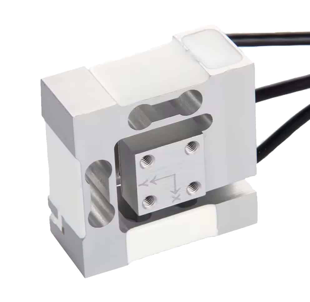
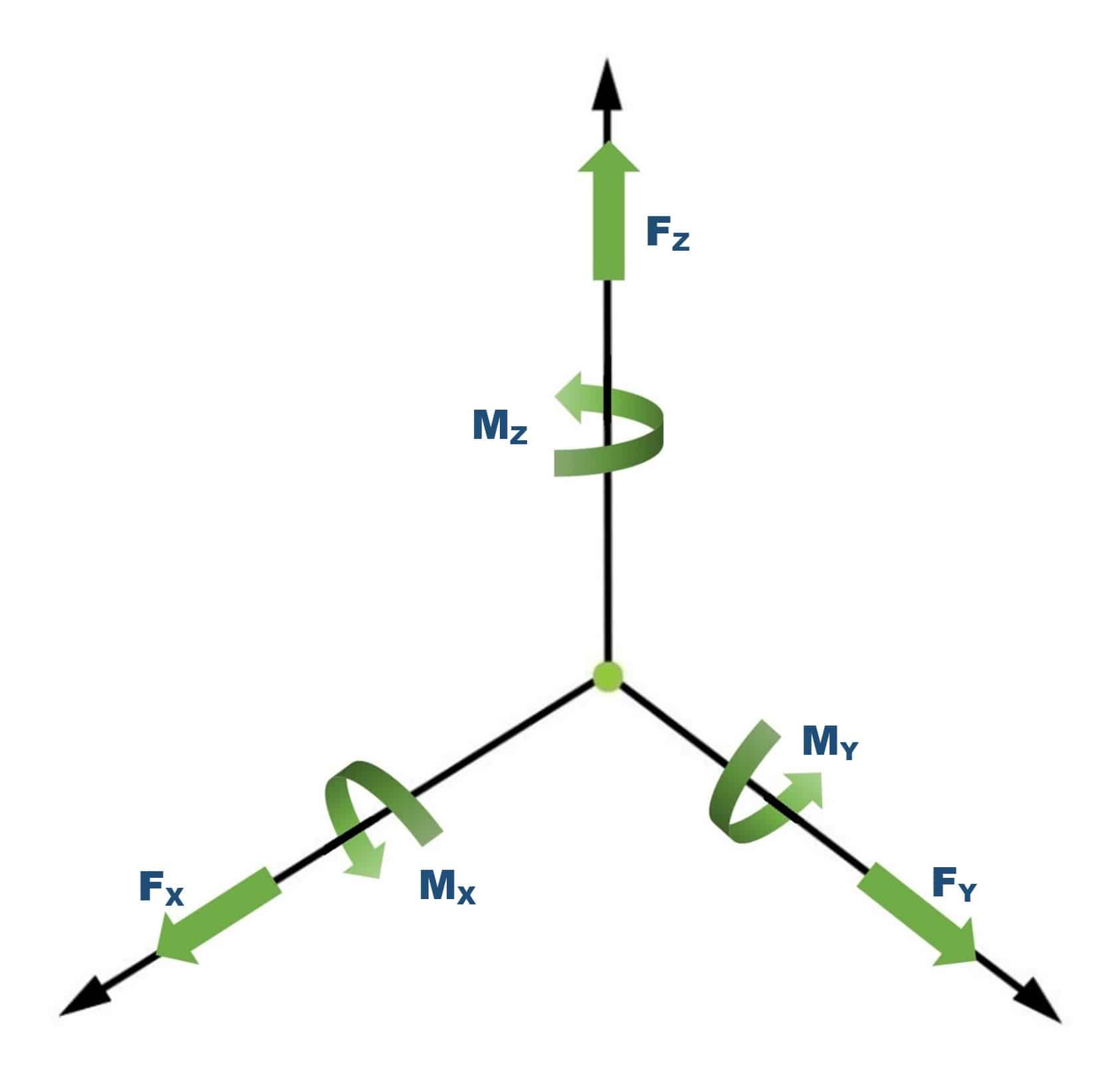
A multi-axis load cell simultaneously measures force components from multiple directions. A 3-axis (triaxial) cell resolves forces on a body or structure into three perpendicular components (\(F_x, F_y, F_z\)). A 6-axis cell adds the three moments (\(M_x, M_y, M_z\)), representing the rotational influences on the body. These cells are essential for engineering applications where the load isn’t purely along a single, known vector, or where quantifying off-axis forces, side loads, and moments critically informs the design.
When a Single-Axis Load Cell Isn’t Enough
Standard load cells are ideal for applications that measure unidirectional forces—tank/hopper weighing, tension monitoring on a crane or winding mechanism, or platform scales, to name a few. This is because they are built to measure force along one axis and to reject all others.
They become less useful when the application has inherent multidirectional forces that can’t be isolated, including:
- A robot gripper that senses contact from unpredictable directions
- A test rig where the specimen pushes back at an angle.
- Aerodynamic or hydrodynamic load sensing on a model.
- Any joint, tool, or end-effector where lateral shear forces and torsional moments impact system stability as much as the primary force vector.
In these cases, a single-axis cell doesn’t simply ignore the off-axis loads. Instead, the side load and moment present as errors on the axis you are measuring, through three distinct mechanisms: cosine error (the on-axis component is reduced by cos θ when the load tilts), direct coupling of the off-axis force into the gauge bridges, and bending moments from eccentric loading (which also add nonlinearity and hysteresis). In contrast, a multi-axis cell intentionally measures each component. This accurately captures all forces on a system at the measuring point.
2-Axis vs 3-Axis vs 6-Axis Load Cells: What Each One Measures
| Type | Measures | Typical use |
|---|---|---|
| 2-axis | Two force components (e.g. Fx, Fy) | In-plane force, simple side-load monitoring |
| 3-axis (Triaxial) | Fx, Fy, Fz — force in all three directions | Contact force, multi-directional testing, robotics |
| 6-axis (Torque Sensor, or Multi-Component) | Fx, Fy, Fz plus moments Mx, My, Mz | Full force/torque applications: precise assembly, robot wrists, biomechanics |
Many applications that ask for “multi-axis” require only a 3-axis cell. That is, they rely on data about where the force is pointing only. Twisting moments are not relevant to their control loops or other functions. When only force direction and magnitude matter, this load cell is the go-to.
But 6-axis, or 6-DOF (degrees of freedom) measurements are standard in applications such as wind-tunnel balances (lift/drag/side force + yaw/pitch/roll), vehicle wheel-force transducers, force-plate biomechanics, as well as fine robotic assembly and wrist force/torque control. Whenever the application’s function or results rely on moments, choose a 6-axis load cell. Also note that the terms “force/torque sensor” and “multi-component load cell” also refer to a 6-axis load cell.
Strain-Gauge vs Piezoelectric Triaxial Load Cells: A Quick Comparison
Triaxial load cells are of two general varieties: strain-gauge sensor-based or piezoelectric sensor-based. Which to choose depends on the type of force being measured.
Thanks to their high stiffness and high natural frequency, piezoelectric sensors excel at measuring dynamic or transient forces. Because their crystalline structure rapidly generates and dissipates electrical charge, they are highly responsive to fast load changes. However, this same charge-dissipation behavior makes them unsuitable for measuring sustained static loads.
Strain-gauge sensors, such as our TSMA load cells, excel at capturing static and quasi-static forces. They operate via Wheatstone bridges, using etched-foil sensors that change resistance under force-induced strain. This produces a millivolt-per-volt (mV/V) output for each axis directly proportional to the load component along that axis. The remainder of this guide covers strain-gauge multi-axis cells.
How a Multi-Axis Load Cell Works
A multi-axis cell is effectively several spring elements fused so that each element’s load path aligns along the X, Y, or Z axis. Each direction features its own Wheatstone bridge of strain gauges. The machined body and gauge orientation work together to isolate forces along each axis: the geometry of the spring element directs stress along the intended load path, while the gauge layout rejects strain from perpendicular directions. Each bridge then outputs a small voltage directly proportional to its component of the total load.
Two consequences follow from that design, and they’re the core reason multi-axis measurement requires more care than single-axis.
One channel per axis: A 3-axis load cell requires three discrete conditioning channels, such as a cluster of three single-channel EMBSGB200 amplifiers or a multi-channel signal conditioner. The three channel readings are not fully independent, however, which leads to the next point.
Crosstalk: In a multi-axis load cell, loading one axis causes minor mechanical deflections that register as small, false readings on adjacent axes. Crosstalk is the term for that residual signal that appears on adjacent axes when isolation isn’t perfect. Well-designed cells keep this error small and, more importantly, characterized, so it can be corrected mathematically in the signal conditioner using a calibration matrix.
Multi-Axis Load Cell Signal Processing: Instrumentation & DAQ
Each axis of a multi-axis cell functions as an independent sensor requiring its own signal conditioning channel. A 3-axis cell, for example, pairs with three dedicated amplifiers (or a 3-channel signal conditioner) to provide excitation voltage and amplification per axis.
Converting raw voltage readings into force units usually requires applying known physical test loads to calibrate the amplifier output. However, you can bypass this physical tuning because all system variables are pre-measured:
$$\text{Output Voltage} = \left( \frac{\text{Applied Force}} {\text{Rated Capacity}} \right) \times \text{Load Cell Sensitivity} \times \text{Excitation Voltage} \times \text{Amplifier Gain}$$
For example, our EMBSGB200 amplifier operates at 5 V excitation, and each board has its exact factory-measured excitation voltage and gain printed directly on the underside. By entering these printed values along with the cell’s certified per-axis sensitivity (found on its calibration certificate) into your DAQ software, you can calculate the exact scaling factor mathematically, skipping the use of test weights or physical gain adjustments.
For wiring and DAQ setup, see Connecting a Force Sensor to a DAQ.
Applying Calibration Matrices to Correct for Multi-Axis Load Cell Crosstalk
To account for mechanical crosstalk, factory calibration evaluates each force axis individually and in combination to generate a multi-dimensional calibration matrix (a 3×3 matrix for a 3-axis cell, or a 6×6 matrix for a 6-axis cell). Software in the system’s DAQ can apply this matrix to the raw load cell channel outputs, mathematically isolating the true force components from their coupled signals as follows:
$$\begin{bmatrix} F_x \\ F_y \\ F_z \end{bmatrix} = [\text{Calibration Matrix}] \cdot \begin{bmatrix} V_x(t) \\ V_y(t) \\ V_z(t) \end{bmatrix}$$
Crucially, the matrix assumes that all voltage inputs represent the same instant in time. Applying the matrix to asynchronous data mixes readings from slightly different moments, introducing mathematical errors into your calculated force vectors. When applied to time-synced, properly scaled data, the matrix successfully decouples off-axis interference, outputting true, crosstalk-corrected force and moment components.
Engineering Note: Improper load cell alignment with the mounting frame introduces cross-axis forces that the calibration matrix will interpret as signal, not error. Correct mounting is therefore a prerequisite for full system deployment, not an afterthought. For detailed matrix math and mounting guidance, see Building a Multi-Axis Force Measurement System.
Force Sensing Applications for Multi-Axis Load Cells
In real-world mechanical systems that experience complex off-axis loads, side forces, and moments, multi-axis load cells provide the complete vector data required to evaluate performance, improve automation control, and guarantee structural safety across advanced testing and operational environments. The table below gives some examples.
| Force Sensing Applications for Multi-Axis Load Cells | ||
|---|---|---|
| Application | Sensor Configuration | Key Role & Measurement Focus |
| Robotic End-Effectors & Grippers | 6-Axis | Enables precise Force-Torque (F-T) feedback for tactile assembly, part insertion, and adaptive contact-force control. |
| Aerospace Wind-Tunnel Balances | 6-Axis | Measures aerodynamic lift, drag, and side forces along with pitch, roll, and yaw moments on scale models. |
| Automotive Wheel-Force Transducers | 6-Axis | Captures real-time tire-road forces (Fx, Fy, Fz) and rotational moments (Mx, My, Mz) during vehicle track testing. |
| Biomechanics & Force Plates | 3-Axis or 6-Axis | Quantifies ground reaction forces and center-of-pressure shifts for gait analysis, ergonomics, and sports performance. |
| CNC Machining, Grinding & Polishing | 3-Axis or 6-Axis | Monitors tool wear, cutting-force vectors, and surface contact pressures to ensure machining precision and prevent tool failure. |
| Materials & Structural Testing | 3-Axis or 6-Axis | Evaluates multiaxial fatigue, shear stresses, and off-axis behavior in complex structural components and non-standard specimens. |
| Medical, Prosthetics & Rehabilitation | 3-Axis or 6-Axis | Measures multi-directional joint loads and weight distribution to optimize prosthetic design and track patient recovery metrics. |
How to Choose the Right Multi-Axis Load Cell: Key Specs and Selection Checklist
Selecting a multi-axis load cell requires an evaluation of factors beyond standard single-axis criteria. Because these sensors measure independent force vectors (and potentially rotational moments) from a single physical structure, you must account for per-axis sizing, crosstalk interference, channel counts, and spatial constraints simultaneously.
Step-by-Step Selection Checklist
- Determine the Required Axes (3-Axis vs. 6-Axis)
- 3-Axis (\(F_x, F_y, F_z\)): Select a 3-axis cell if you only need to measure force magnitude and direction in 3D space.
- 6-Axis (\(F_x, F_y, F_z, M_x, M_y, M_z\)): Select a 6-axis cell if your application involves twisting, off-center loading, or moments that must be quantified (such as robotic arm end-effectors or wind-tunnel models). Avoid paying for the additional moment channels and their conditioning if your setup does not require them.
- Size Capacity Per Axis
- Multi-axis load cell capacities are stated per individual axis and are often asymmetrical (for instance, a higher vertical \(F_z\) capacity than lateral \(F_x/F_y\) capacities).
- Rate each axis for its maximum anticipated component force, ensuring sufficient headroom for dynamic transients, impact spikes, or off-axis loads.
- Verify Size, Mass, and Mounting Constraints
- Applications such as robotic grippers, medical devices, and flight test fixtures have severe space and weight limits. Excessive load cell mass adds unwanted tare weight and inertia to dynamic systems. In these cases, look for compact or miniature multi-axis load cells designed for tight mounting envelopes.
- Budget for Conditioning and DAQ Channels
- Remember that a multi-axis sensor is functionally multiple load cells fused into a single body. A 3-axis cell requires three independent signal conditioning channels (or three individual amplifiers); a 6-axis cell requires six.
- Ensure your Data Acquisition (DAQ) system can log all channels time-synchronously so your software can apply the calibration matrix accurately.
- Evaluate Environmental Exposure
- Consider ambient temperature swings, chemical exposure, outdoor elements, or washdown requirements. Select an appropriate IP rating and check thermal shift specifications to prevent environmental drift.
Decoding Multi-Axis Datasheet Specifications
While our guide, How to Read a Load Cell Datasheet, covers basic single-axis parameters, multi-axis datasheets give a different context to these same parameters. They also include unique parameters, all of which require comparison to choose the right load cell:
- Capacity (per axis): The maximum rated load for each individual axis (\(F_x, F_y, F_z\) in Newtons or \(\text{lbf}\); \(M_x, M_y, M_z\) in \(\text{N}\cdot\text{m}\) or \(\text{lb}\cdot\text{ft}\)).
- Rated Output (mV/V): The full-scale output voltage per volt of excitation, specified for each axis individually.
- Crosstalk (%): The percentage of full-scale output induced on an un-loaded axis when a full-scale load is applied to an adjacent axis. Lower native crosstalk yields cleaner raw data prior to software matrix correction.
- Combined Error: The aggregate measurement uncertainty per axis, combining non-linearity, hysteresis, and repeatability into a single percentage of full-scale output (% FSO).
- Safe / Ultimate Overload: Expressed as a percentage of rated capacity per axis (typically 150% safe, 300% ultimate). Exceeding the safe overload on even a single axis can permanently deform all of the flexures (spring element branches).
- Zero Balance: The electrical output of each bridge when no force is applied, typically expressed as a percentage of rated output (\(\pm 1\%\) to \(\pm 5\%\) FSO).
- Cabling, Pinout & Connectors: Because multi-axis cells house multiple independent Wheatstone bridges, cabling will feature multi-conductor shielded cables or multi-pin circular connectors. Verify pinouts to ensure compatibility with your junction boxes or multi-channel amplifiers.
- Operating Temperature & Thermal Effects: Specifies the safe operating temperature window alongside the Thermal Effect on Zero and Thermal Effect on Span (% FSO per °C/°F) for each axis.
- IP Rating: Defines the mechanical sealing against dust and liquid ingress (e.g., IP65 for splash resistance, IP67/IP68 for immersion).
Conclusion & Next Steps
Multi-axis load cells are a sound solution where clear vector data is needed in complex, multidirectional force environments. Whether you are balancing an aerodynamic test model, controlling a robotic wrist end-effector, or conducting multiaxial fatigue testing, matching your force/torque requirements to the correct sensor topology is critical to obtaining useful measurements.
When physical space is limited, compact strain-gauge units deliver industrial accuracy without adding unwanted system inertia. Tacuna Systems offers off-the-shelf multi-axis force solutions designed for tight mounting envelopes, including our TSMA110 3-axis series (covering \(10\text{ N}\) to \(2000\text{ N}\) / \(\approx 2.2\) to \(450\text{ lbf}\)) and the higher-capacity TSMA220 line (extending force measurement up to \(5000\text{ N}\) / \(\approx 1124\text{ lbf}\)). However, selecting the sensor is only the first phase of system integration. Turning raw microvolt outputs into crosstalk-free force vectors requires careful mechanical alignment, multi-channel excitation, and real-time matrix math execution in your DAQ software.
Ready to build your end-to-end multi-axial measurement system? Read our step-by-step engineering guide, Building a Multi-Axis Force Measurement System, to learn how to wire multi-channel amplifiers, construct time-synchronized data pipelines, and apply calibration decoupling matrices in code.