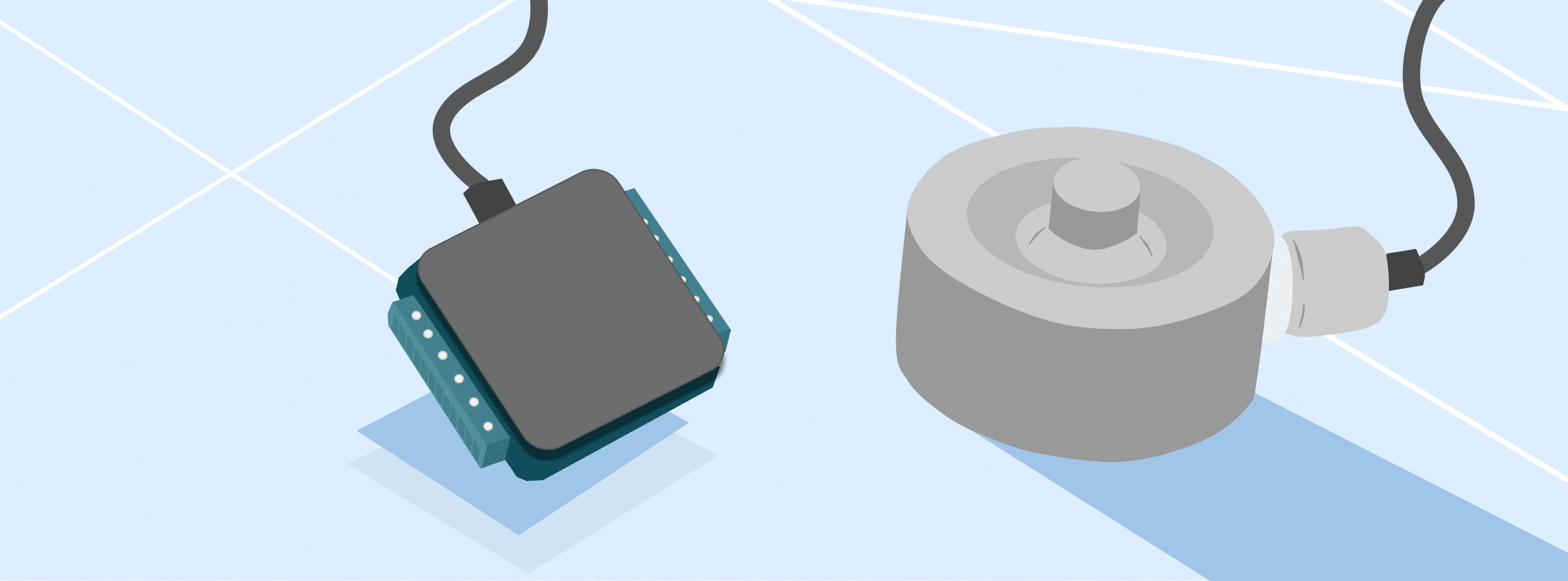
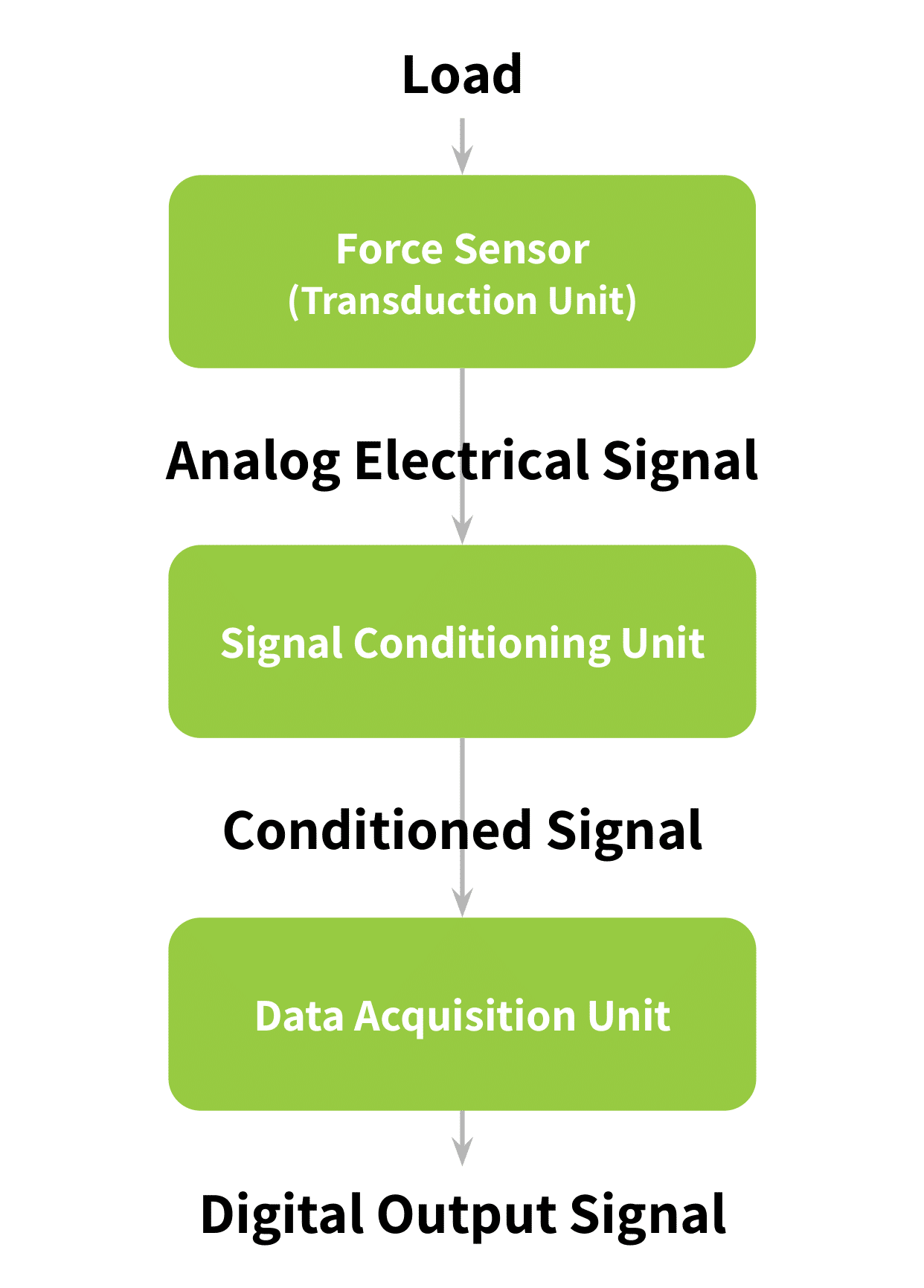
When connecting a force sensor and data acquisition (DAQ) system, understanding how all the related subsystems integrate is helpful. The block diagram in Figure 1 below shows these individual components and how a signal flows through them. This document describes the function of each block pictured. It concludes with a description of the various subsystems of the sensor-DAQ setup using some of Tacuna System’s devices for reference.
Key Takeaways
- The article explains the process of connecting force sensors to a DAQ system, detailing the function of each component involved.
- Force sensors, like strain gauges and hydraulic sensors, convert physical forces into electrical signals for measurement.
- Signal conditioners isolate, filter, and amplify signals to prepare them for the DAQ.
- The DAQ unit processes signals through anti-aliasing filters, sample and hold circuits, quantizers, and digital signal processors.
- Tacuna Systems offers a range of signal conditioners for this purpose, and an innovative DAQ system through our affiliated organization, DAQifi.
The Force Sensor/Transduction Unit
A sensor detects a physical phenomenon and transforms the detected quantity into a proportional output through a process called transduction. This output might be pneumatic, mechanical, or electrical. Force transducers exploit principles of physics to generate electrical signals when they experience a physical force. They are classified depending on the physical principle used. The following are some common types of force sensors: hydraulic, pneumatic, capacitive, and strain gauge. (See An Overview Of Load Cells, and The Versatile Strain Gauge Load Cell for more information about these sensors.)
Hydraulic Force Sensors
The hydraulic force sensor works on the principle of force-balance. It uses a piston and a liquid contained in a sealed cylinder chamber to sense the applied force. The piston-fluid interface then transmits the force exerted on the loading platform to a pressure indicator or a pressure transducer. The pressure transducer, as the name implies, converts the pressure to an electrical signal.
Pneumatic Force Sensors
The pneumatic type of force sensor also works on the same principle of force-balance. However, instead of using a liquid, it works with compressed air or gas.
Capacitive Force Sensors
The capacitive type senses force through the change in capacitance of a material between two charged plates, as the the distance between the plates changes. One plate is stationary while the other is movable. The force exerted on the moveable plate decreases or increases its distance from the stationary plate. This produces an output capacitance proportional to the applied force.
Strain Gauge Force Sensors
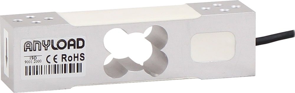
The most common of the sensors mentioned in this article is a strain gauge load cell. This sensor uses an elastic resistive material called a strain gauge, attached to a rigid structural member. When a force is applied to the load cell at a specific point, the gauge’s structural member experiences a mechanical strain. The strain gauge deforms elastically under this strain, producing a change in resistance.
All strain gauges require an excitation voltage at the input. The change in resistance changes this voltage. Using a Wheatstone bridge circuit, the change in voltage due to strain produces an output signal. A strain gauge load cell has typically four wires: two power supply/excitation wires and two output signal wires.
The Signal Conditioning Unit
This is the intermediary unit between the force sensor and the DAQ. It converts the output from the transduction unit to a signal compatible with the data acquisition unit. This signal conditioning process generally follows three steps: isolation, signal filtering, and signal amplification.
Isolation
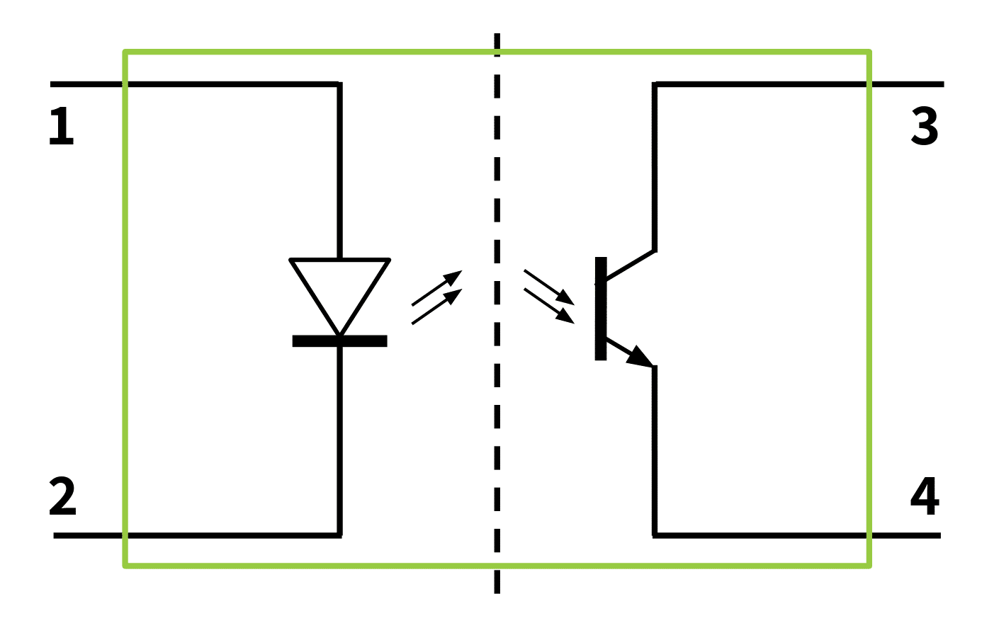
In the case where the load cell excitation signal comes from a regulated supply on the signal conditioner circuit, an electrical isolator is necessary. This device isolates the force sensor from a direct connection to the power supply, protecting the sensor from fault currents. Isolation can be done by a magnetic isolator such as a transformer, or an optical isolator such as an optocoupler.
Signal Filtering
This step is important when using a strain gauge transducer. The output signal from a strain gauge can be very small (in the order of millivolts, mV), and potentially “noisy”. The DAQ requires a clean, detectable input signal. The process of signal filtering removes this noise, or unwanted signals from the sensor output.
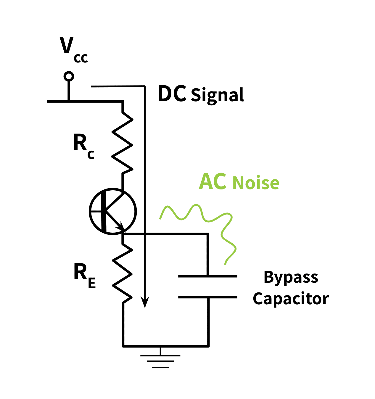
Signal filtering is done using specially designed circuits such as active and passive filters. Alternatively, one can place a bypass capacitor between the positive terminal of the signal path and the ground terminal of the signal path. This capacitor serves as a low pass filter since it conducts high-frequency signals (such as AC noise) to ground.
Filtering is always necessary at both the the amplifier input and output.
The Signal Amplifier
Amplification is the last step of signal conditioning. The amplifier increases the dynamic range of the filtered sensor output to a level equal to or near the dynamic range of the DAQ.
Generally, two methods exist to amplify the sensor output signal.
1. Differential Amplifier
With this method, the output terminals from the sensor become part of a voltage divider circuit. A differential amplifier then amplifies the voltage divider output.
2. Instrumentation Amplifier
With this method, the sensing device (typically a strain gauge) is in an arm of a Wheatstone bridge. The output terminals of the bridge connect to an amplifier. The most commonly used amplifier in the industry is the Instrumentation amplifier. Its advantages over the differential amplifier include its high and stable gain value, very high input impedance, very low output impedance, and an extremely high common-mode rejection ratio. The low output impedance in turn presents a low input impedance signal source to the DAQ. This prevents changes in the input of the DAQ from altering the output from the amplifier.
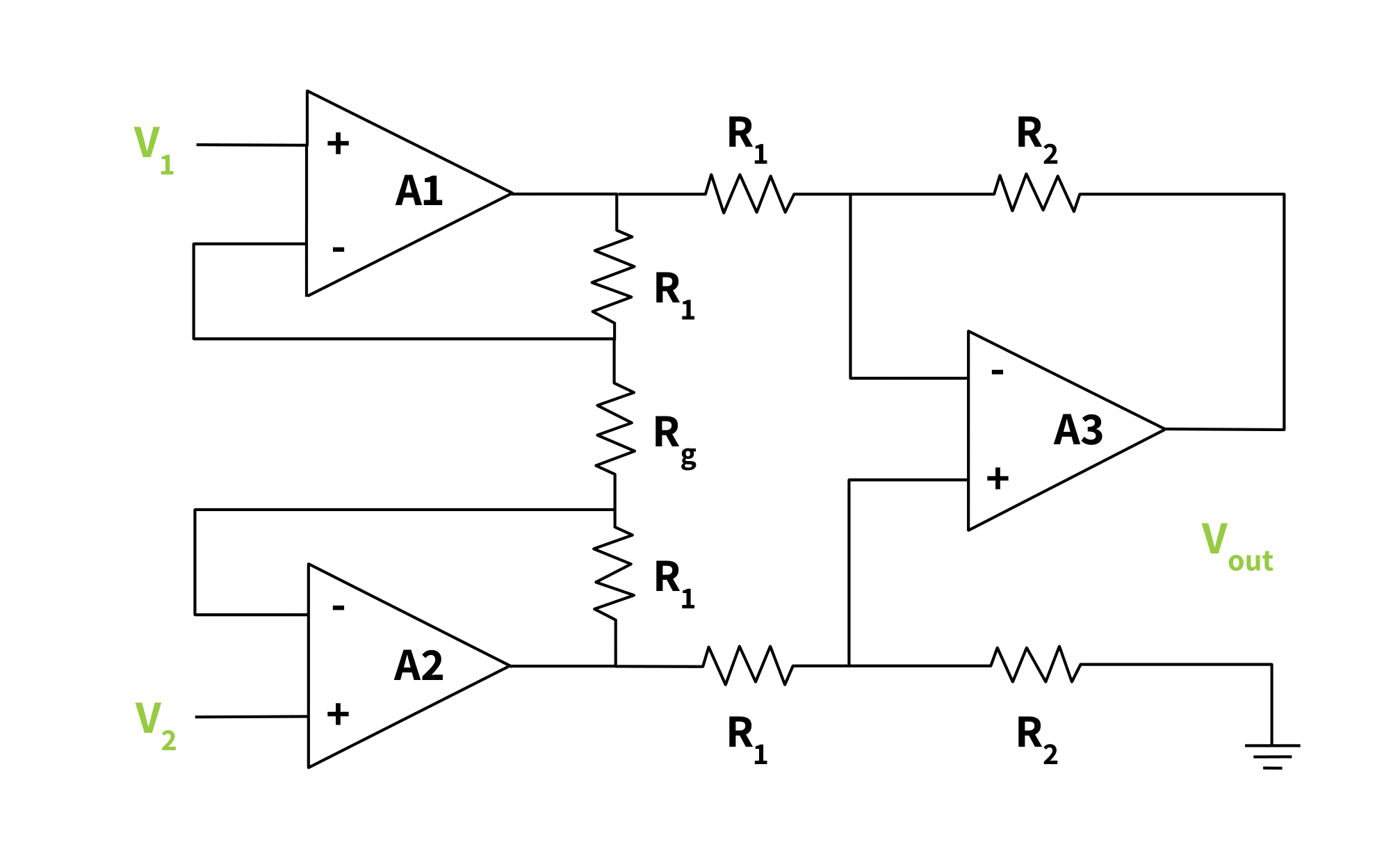
\(V_{out}=left ( V_{2}-V_{1} right )(1+frac{2R_{1}}{R_{g}})+(frac{R_{2}}{R_{1}})\)
Signal Conditioning, Summarized
We can summarize the internal workings of the “Signal Conditioning Unit” block in Figure 1 as follows:
- The power supply to the load sensor is isolated,
- Noise is filtered from the load sensor output voltage, and
- The filtered signal is amplified to a level compatible with the requirements of the DAQ.
The Data Acquisition (DAQ) Unit
This unit receives the conditioned signal from the force sensor. It consists of the following digital signal processing units:
- The anti-aliasing filter,
- The sample-hold (S-H) circuit,
- The quantizer-encoder circuit, and
- The digital signal processor.
The Anti-Aliasing Filter
This is the analog filter circuit located directly at the output terminal of the amplifier. It band limits the DAQ unit’s input received from the amplifier circuit. This band limiting is necessary to remove any frequency components that are higher than half of the DAQ’s sampling frequency. Without the anti-aliasing filter, the DAQ’s sampling would occur at inappropriate intervals for these higher frequencies. This would produce a sampled signal containing various overlapping or indistinguishable frequency components. Aliasing is the term for this overlapping effect.
The Sample and Hold Circuit
This component performs sampling. “Sampling” is the measuring of an analog signal’s amplitude at discrete time intervals to produce a sequence of samples. The term “sampling rate” refers to these discrete time intervals. This rate must be at least the Nyquist Limit (twice the signal’s highest frequency component).
The Nyquist Theorem states that an input analog signal is accurately reconstructable from its sampled version if sampling occurs at a rate that is at least twice its highest frequency component. This explains the need for an anti-aliasing filter. This filter limits the analog signal from the amplifier to a bandwidth lower or equal to half of the sampling rate.
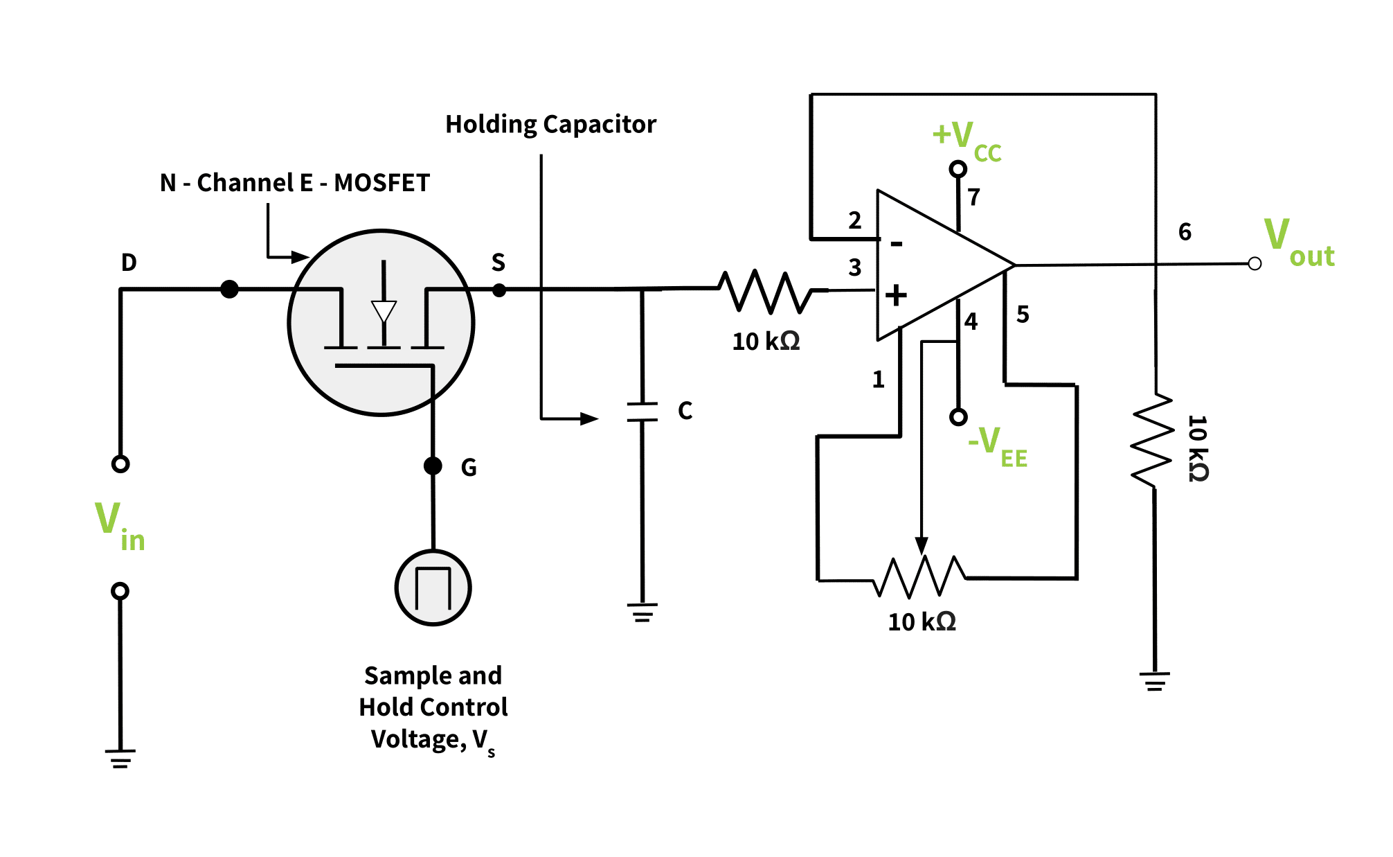
The Sample and Hold circuit (S-H) consists of a solid-state high-frequency switch, a holding capacitor, and a buffer amplifier (i.e., a voltage follower).
In practice, the S-H circuit is very key to the sampling process because the input analog signal is time-varying. To truly sample this signal, the component must determine the instantaneous frequency value at each specific time. The circuit holds the instantaneous value steady till the next time interval. The held signal value must be sampled within that holding time period at the appropriate sampling rate to achieve an accurate result.
Figure 6 below shows a simple S-H circuit. This unit converts the analog signal into a discrete-time signal continuous in amplitude but discrete in the time domain.
The Quantizer and Encoder
The quantizer unit samples the S-H output in the amplitude domain. Quantization creates a range of equally spaced levels. Each signal level exists between only two possible limits; hence the term quantized.
The encoder then assigns a certain binary code to each of these levels. The encoder can use one of two possible encoding schemes: the two’s complement coding scheme or the offset binary coding scheme. Both are ways to represent signed integers (positive versus negative) in binary code.
Note that the S-H circuit, the quantizer and the encoder together all form an analog-to-digital converter (ADC). This is so because the input to the S-H circuit is analog and the output from the encoder is digital.
The Digital Signal Processor (DSP)
This component performs certain processing operations on the digital signal: frequency and time domain analysis, filtering, convolution, and correlation.
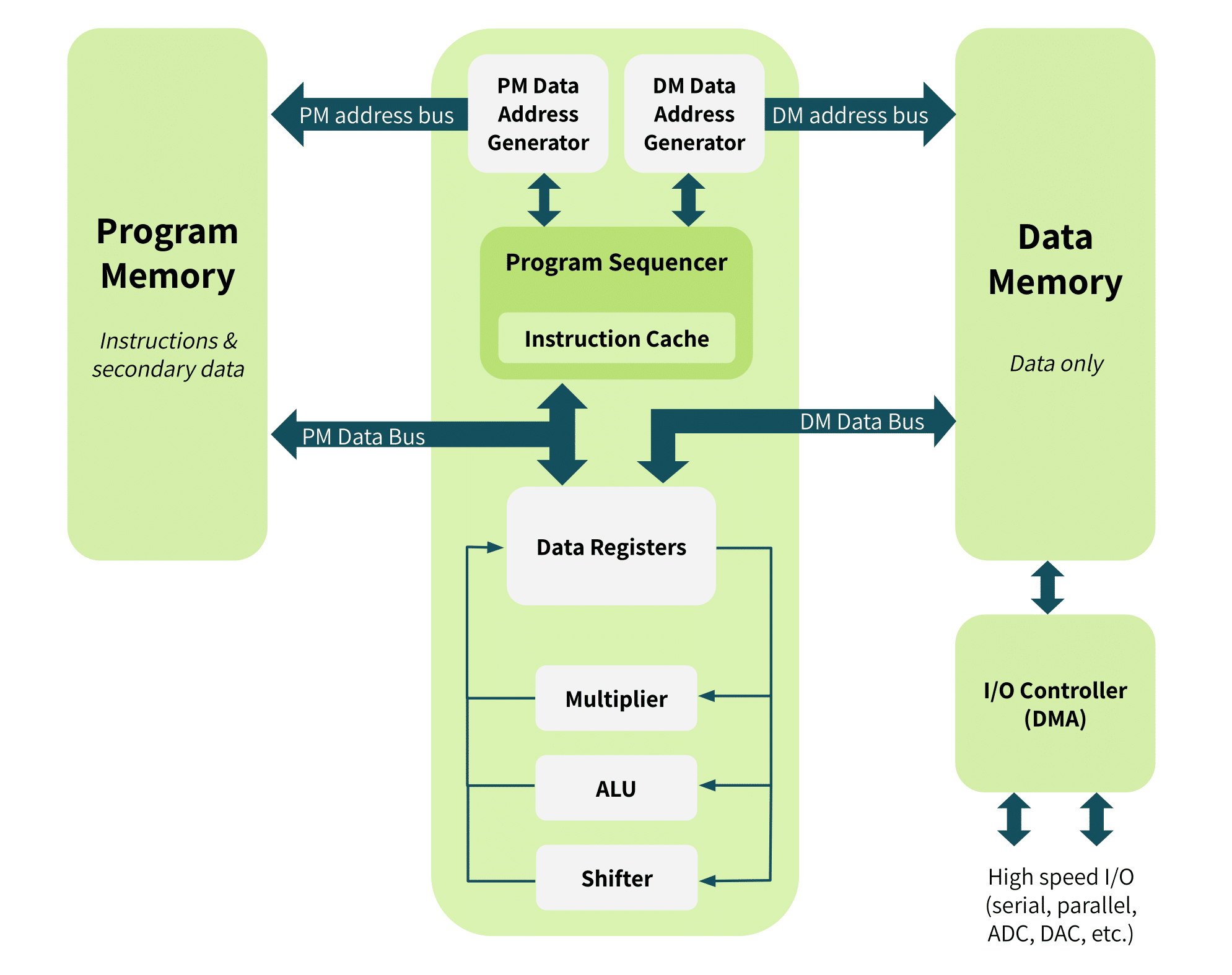
The DSP is a unit that has its own subsystems. Also, it runs on a dedicated hardware architecture that is quite similar to that of a general microprocessor. The special hardware unit of the DSP includes multipliers, an accumulator unit, shifters, address generators, data memory, and program memory. The DSP memory stores the digitized signal for later retrieval by processes such as display or process control.
Figure 7 shows the architecture of a DSP.
A Look at Hardware Products
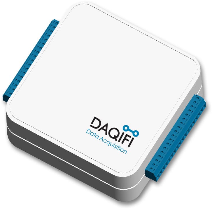
The data acquisition hardware shown in Figure 8 below is a portable device that can aggregate input from several sensors. It has 16 input channels and a sampling rate of up to 1000Hz. It include a data logging system, and offers both wired and wireless telemetry transmission.
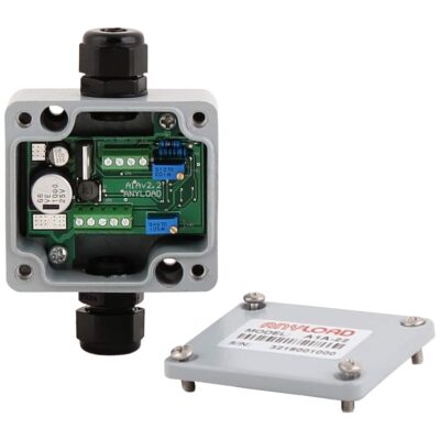
A starting point for the other devices described in this article is the Tacuna Systems online catalog. Tacuna Systems offers a wide range of amplifiers and conditioners that prepare load cell signals for input to this DAQ. Figures 9-10 below show one such amplifier in our catalog and its datasheet specifications.
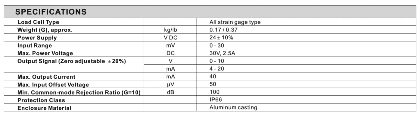
The datasheet shows the amplifier gain, the load cell type it supports, the input range it supports from a sensor, and the output voltage and current. Note that the output voltage and current signal value all fall within the dynamic range of the DAQ device.
Tacuna Systems offers an in-house designed amplifier product that offers bridge completion and factory-calibrated gain. Available in three options, it is our most popular and highly-rated amplifier. See How the EMBSGB200 Amplifier is Shaping Innovations in Technology and Industry and Next-Gen Transmissions for High-Performance Hybrid Cars for examples of how our customers have used this versatile device.
Our customers find that acquiring all system components from our suite of products reduces the time from order placement to up-and-running. This is because we offer complimentary design support with a complete package of compatible force measurement components, eliminating guesswork or trial and error.
Conclusion
This article has explained the internal workings of each component in the signal path from a force sensor to, and including, a data acquisition system. Also, it has given product examples for readers searching for these systems to begin their comparison.
The DAQ output is useful in several forms, depending on the last component in the overall measuring system. Its output can signaled to a simple readout to provide information to human operators. The DAQ output can also be the input of control systems in industrial processes. Finally, the DAQ can incorporate a telemetry system to transmit the digitized measurement accurately over long distances to remote locations. See Advantages and Applications of Wireless Load Cells.