

Piezoelectric force transducers are essential tools for capturing precise, real-time force measurements in compact, high-frequency applications. Their small size, sensitivity, and ability to measure dynamic forces make them indispensable in industries where these attributes matter most (such as robotics). Like all other sensors, their accuracy requires strict adherence to the proper installation steps. In this article, we cover the necessary electrical modeling, mounting procedures, and signal conditioning setup for installing piezoelectric force sensors (including calibrated pre-loading, thermal isolation, ultra-high-impedance cable management, and proper charge amplifier matching).
Key Takeaways
- Dynamic Load Focus: Piezoelectric force transducers generate electrical charge proportional to applied force, making them essential for compact, high-frequency measurements such as robotics, modal testing, and shock monitoring.
- Pre-Loading & Surface Specs: Accurate measurement requires mounting surfaces hardened to \(\ge 50\text{ HRC}\) and ground flat and parallel (\(\le 0.8\ \mu\text{m}\ Ra\)). Transducers measuring tension, shear, or alternating loads must be pre-loaded to 20%–50% of their rated capacity.
- Resonance & Thermal Protection: Because stiff piezoceramics ring at natural resonant frequencies up to 100,000 Hz without self-damping and drift under thermal shock, installations require mechanical damping, thermal isolation, and sealed vacuum housing.
- Low-Noise Cabling & Proximity: High-impedance charge signals demand graphite-treated, low-noise coaxial cables firmly anchored within 5 to 10 cm of the housing, feeding a charge amplifier located less than 3 meters away to minimize line capacitance and EMI.
- Cleanliness & System Verification: Contaminants like oil or moisture on output terminals create charge-leakage paths that ruin accuracy. Installation requires strict cleanliness, pre-installation insulation checks, post-installation noise-floor verification, and reference load cell calibration.
What is a Piezoelectric Transducer?
A piezoelectric force transducer is a sensor that generates an electrical charge proportional to an applied force using the piezoelectric effect. This charge converts to an electrical signal at its output terminals.
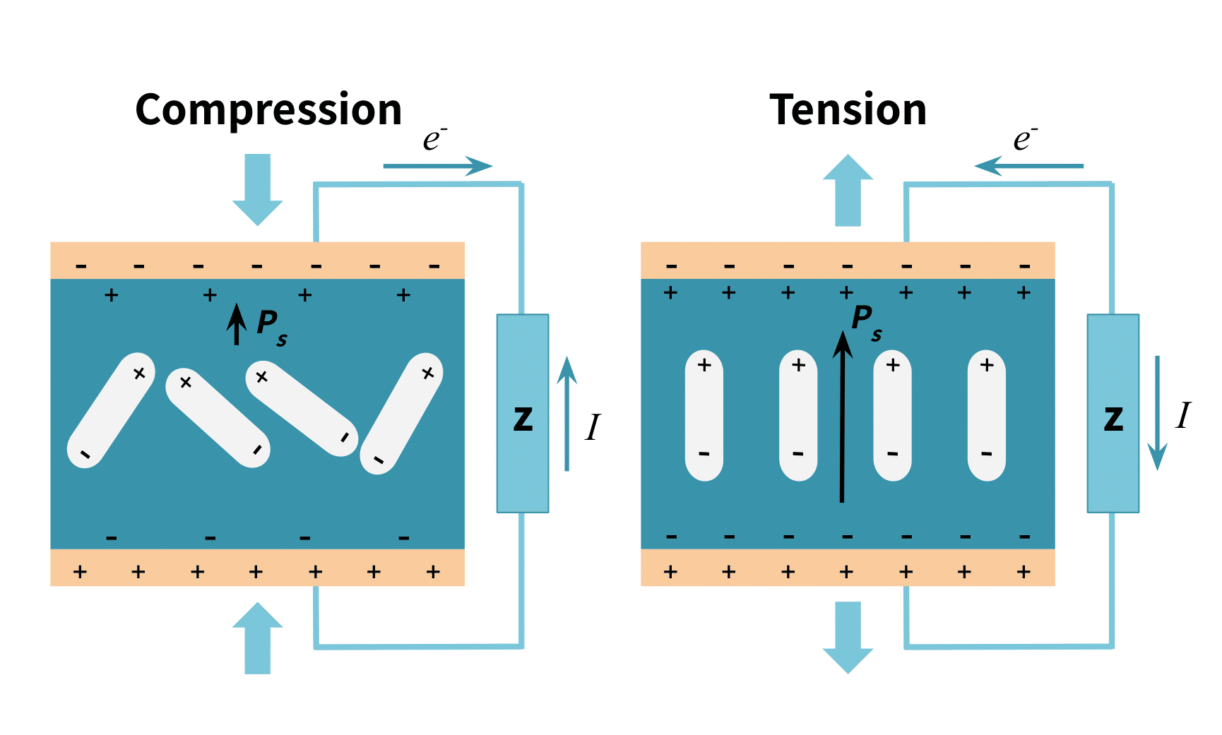
This piezoelectric effect occurs in polarized crystalline materials under stress or deformation. The stress causes a shift in the material’s molecular geometry, creating (in a natural crystal) or altering (in a manufactured one) its polarity. It is similar to di-electricity, which occurs when a charge is produced from a shift of electrons in an insulator.
A decreased polarity creates a current in the direction of the crystal’s polarity, while an increased one creates an opposite current. Figure 1 below illustrates this effect, where \(P_{s}\) indicates the polarity and the length of its vector indicates its strength.
In an electrical schematic diagram, a piezoelectric force sensor appears as a charge source in series with a capacitance that has an internal resistance and inductance. Figure 2 below illustrates this.
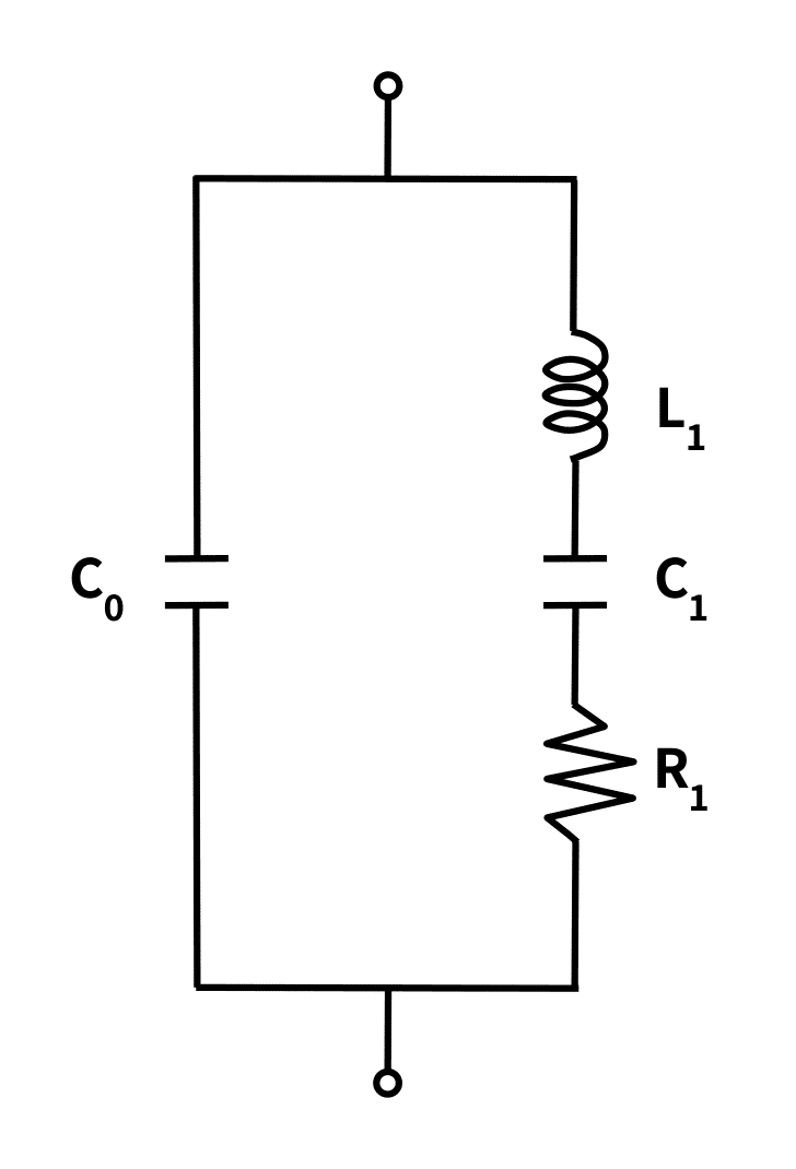
Where the equivalent electrical parameters represent:
- \(L_1\) = Serial Inductance (sensor mechanical mass equivalent)
- \(C_1\) = Serial Capacitance (mechanical compliance equivalent)
- \(R_1\) = Serial Resistance (internal mechanical damping)
- \(C_0\) = Parallel Capacitance (dielectric capacitance of ceramic/crystal and electrodes)
- \(C_f\) = Free Capacitance (\(C_f = C_0 + C_1\))
The mathematical model for the relationship between the charge produced, the applied force, compliance, and the material constant appears below. The compliance of the material is the inverse of Young’s modulus.
\(q=a\cdot F\cdot K_{s}\)
Where \(q\) is the electrical charge generated by force, \(F\) (in Newtons) applied across the faces of a piezoelectric device with a mechanical compliance of spring rate \(K_{s}\) (\(mN^{-1}\) ) and a more complex material constant, \(a\) , of dimensions \(C\) \(m^{-1}\) .
The piezoelectric material lies along the transducer’s loading axis—that is, the imaginary line along the direction, and at the application point, of the measured force.
Installing a Piezoelectric Sensor
Key Mounting and Mechanical Design Considerations
As with any application, the engineering phase of any piezoelectric sensor application requires attention to some key considerations. This is especially true since piezoelectric ceramics deform by less than a few micrometers under full scale, meaning the surrounding mechanical interface strongly influences signal accuracy and sensor fatigue life.
- Sensor Accessibility: System design should place the sensor where it can easily be reached or removed for repairs and maintenance.
- Loading Axis Alignment: The sensor orientation should align it’s polarity along the loading axis, and allow the primary force vector to pass through the geometric center of the sensor face. Non-axial side loads or bending moments introduce significant measurement errors and shear stress. Also, the electrodes that detect the crystal’s field must be perpendicular to the direction of applied stress. Since the transducer’s shape will affect the orientation of the underlying piezoelectric material, and therefore the orientation of the output electrodes, designs should account for this geometry.
- Surface Flatness & Parallelism: Mounting surfaces must be hardened (\(\ge 50\text{ HRC}\)), ground flat, and parallel to within \(\le 0.8\ \mu\text{m}\ Ra\). Surface irregularities create localized point-loading that can crack brittle PZT ceramic elements.
- Resonant Frequency and Damping: Since piezoelectric materials are extremely stiff, they “ring” at their resonant frequencies (sometimes as high as 100,000 Hz) with no self-damping. This can skew measurements significantly. To avoid this effect, designs should use mechanical mounting to suppress high-frequency ringing and isolate sensors from ambient vibration. This key feature keeps the sensor from operating near its resonance peak.
- Calibrated Pre-Loading (Pre-Stressing): Piezoelectric washer and button transducers operate strictly in compression. Designs that measure tension, alternating dynamic loads, or shear forces, should mount the transducer with a high-strength pre-load bolt (typically torqued to 20% to 50% of the sensor’s measuring range). Pre-loading ensures continuous mechanical contact and improves linear response across zero-crossings.
- Sensor Housing: Because piezoelectric sensors are very sensitive to even slight movements, the sensor should be housed in a sealed vacuum once installed to avoid air loading. This also improves damping measures and prevents particle or moisture intrusion.
- Low-Noise Cable Selection & Microphonics: High-impedance charge signals are highly sensitive to triboelectric noise (charge generated by friction when standard cables bend). Designs should specify graphite-treated, low-noise coaxial cables firmly anchored within 5 to 10 cm of the transducer housing. Note: Altering the cable length after installation changes the capacitance; therefore cutting or adding cabling requires compensation for the new capacitance.
- Charge Amplifier Proximity: Design the charge amplifier or ICP/IEPE signal conditioner as close to the sensor as possible (less than 3 meters for charge-mode) to minimize line capacitance, thermal noise, and electromagnetic interference (EMI).
- Thermal Shock & Transient Isolation: Rapid ambient temperature shifts cause thermal expansion strains that manifest as low-frequency signal drift (pyroelectric noise). Include thermal insulating washers or heat shields in designs that operate in high-temperature environments.
- Grounding and Shielding: Designs should include proper sensor shielding from ambient AC voltages and EMI that could induce the reverse piezoelectric effect. As with all other electronics, these applications must properly ground these delicate sensors, avoiding ground loops.
On Site Mounting and Installation: The Right Technician
Even a well-planned, well-documented design relies entirely on qualified personnel for its execution. Installing a piezoelectric transducer requires a technician who understands its specialized installation protocols: verifying the mounting location, sealing the protective housing, grounding the system, and following all wiring schematics. Crucially, technicians must maintain absolute cleanliness during all connector assembly; any oil, dust, or moisture on terminals creates charge-leakage paths that severely compromise measurement accuracy. Installers should also be skilled in pre-installation insulation testing and post-installation noise-floor verification.
Once the sensors are in place, the technician should perform system calibration using a reference load cell to identify systematic errors and verify charge amplifier scale factors.
The Piezoelectric Sensor Data Sheet: Key Specifications
The following specifications should appear on a piezoelectric sensor’s manufacturer’s datasheet.
| Datasheet Specification | Engineering Definition | Application Impact |
| Charge Sensitivity / Distortion Constant (\(d_{ij}\)) | Electrical charge generated per unit applied force (\(\text{pC/N}\)), or strain per unit field. | The most critical metric for sensing. Determines the required charge amplifier gain settings and minimum force resolution. |
| Voltage Output Coefficient (\(g_{ij}\)) | Effective electric field strength generated under uniform stress. | Determines the open-circuit voltage generated by the sensor. Useful if utilizing voltage-mode amplification instead of charge mode. |
| Electromechanical Coupling (\(k\)) | Ratio of converted electrical/mechanical energy to the total input energy. | Higher \(k\) values yield higher sensor sensitivity, wider bandwidths, and better overall energy conversion efficiency. |
| Relative Dielectric Constant (\(\epsilon_r\)) | Ratio of the material’s permittivity to the permittivity of a vacuum. | Dictates the internal capacitance of the sensor. High capacitance improves the sensor’s ability to measure low-frequency dynamic events. |
| Resonant Frequency (\(f_r\)) | Natural mechanical vibration frequency of the unmounted crystal/ceramic. | Operational dynamic forces should remain below 20% to 30% of \(f_r\) to prevent resonance peaks and false force spikes. |
| Mechanical Quality Factor (\(Q_m\)) | Sharpness of mechanical resonance and the material’s internal damping capability. | High-\(Q\) materials exhibit narrow resonance bands but ring longer; low-\(Q\) materials damp vibrations faster, which is useful in noisy environments. |
| Curie Temperature (\(T_c\)) | The temperature threshold where the ferroelectric ceramic loses its polarization. | Exceeding \(T_c\) causes a permanent loss of piezoelectric properties. Operating temps should usually stay below half of \(T_c\). |
| Compliance (\(s^E\)) | The ratio of strain to stress (the inverse of Young’s Modulus). | Defines the “spring rate” or stiffness of the sensor. Critical for calculating the total mechanical stiffness of a pre-loaded bolted assembly. |
| Poisson’s Ratio (\(\nu\)) | Ratio of transverse (lateral) strain to axial strain under constant stress. | Impacts how the sensor reacts to off-axis forces. High values can increase unwanted cross-axis sensitivity if not mounted perfectly flat. |
| Insulation Resistance (\(R_{ins}\)) | Internal dielectric resistance across the sensor’s output terminals (\(\ge 10^{12}\ \Omega\)). | Low resistance accelerates charge leakage (drift). High \(R_{ins}\) is absolutely critical for maintaining accuracy at low frequencies. |
Conclusion
Installing piezoelectric force transducers successfully requires rigorous mechanical preparation, including precision surface grinding, pre-load torque calibration, and low-noise coaxial cable routing, with high-impedance charge amplification. When properly mounted, piezoelectric transducers provide unmatched frequency response for shock wave monitoring, modal testing, and high-speed robotic force control.
For assistance selecting load cell mounting hardware, signal conditioners, or custom sensor setups, contact the Tacuna Systems engineering team.
Other Resources:
- An Overview of Load Cells
- The Piezoelectric Effect and Its Applications
- Comparing Strain Gauges to Piezoelectric Sensors
- Load Cells and Force Sensors in Robotics
- Connecting a Force Sensor to a Data Acquisition Sensor DAQ
- Load Cell Mounting and Installation Best Practices