
Industrial weighing systems like tanks, hoppers, or fillers need to be accurate in often challenging environments. Choosing the best load cell of the highest quality is the first step in achieving this accuracy. However, proper load cell installation and mounting are equally important. Careful design and construction of the load cell mounting frame result in repeatable, proper load alignment. Correct installation also guarantees a longer system lifespan and safe operations.
This article gives helpful load cell installation tips and important factors to consider. However, it does not replace an installation guide. Always follow the manufacturer’s installation instructions and use certified installers. Still have questions? We encourage you to contact Tacuna Systems for any design or implementation issues specific to your project.
Key Takeaways
- Proper measurement system planning and load cell installation are vital for accurate measurements and safe operations.
- Choose the right frame and fixture to maximize load cell performance and safety, and minimize environmental interference.
- Build the structure so that loads are axially aligned and avoid force shunts to achieve accurate readings.
- Protect against environmental factors like temperature extremes, vibration, wind, and moisture that can affect load cell reliability and structural safety.
- Use hardware appropriate for the environment and maximum loading.
- Follow the manufacturer’s installation guidelines to ensure system reliability.
1) Start by Designing the System’s Frame and Fixture for Safety and Load Cell Accuracy
Planning the proper fixture (or load cell mount) and frame is a critical first step for accurate load cell performance and safe operating conditions.
An optimal frame design should maximize stiffness but minimize weight and costs. The frame must be sturdy enough to support the maximum weight borne by the measuring device (including overload). It should also be rigid enough to withstand deformation and flexing. The structure’s supporting features should be rigid.
The fixture design should minimize the environmental challenges described below to avoid unintended load inputs and damage to the load cell.
(a) How to Mitigate Vibration
Many factors can introduce vibrations, including compressors, pumps, actuators, and engines. Additionally, ground vibrations from seismic activity can skew measurement results. Secure the frame to a hard, flat surface to reduce vibrations from passing vehicles and local machinery. Also, factor in vibration when choosing mounting hardware to prevent loosening bolts from creating an unstable frame.
To the extent that vibration mitigation is not possible, run the load cell output signals through filters and software to compensate for the effect (see Section 4 below).
(b) Allow for Thermal Expansion/Mechanical Deformation
Design the mounting frame with clearances that allow for unhindered thermal expansion or contraction. Load cell mounts that limit mechanical expansion can cause permanent damage to the load cell or frame. This, in turn, can cause structurally unsafe conditions.
Including weigh modules in the design can help considerably.
(c) Include Devices to Avoid Rotation in Suspended Systems
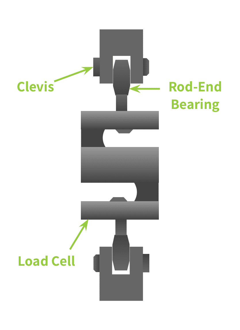
For suspended loads, the mounting frame should limit rotation to prevent hardware from loosening over time. Several devices serve this purpose, including clevis ends (see Figure 2 below) and check rods.
(d) Engineer to Account for Other Environmental Forces
Particularly in outdoor environments, the support frame must account for other forces that can add loads to the system, such as wind and loading shocks. Include overload stops or weigh modules to mitigate damage to load cells and the frame. The article, A Comparison of Tacuna Systems Load Cell Mounts summarizes the features of each such mount we sell to help with the selection process.
Likewise, moisture or debris intrusion can corrode or rupture both structures and the load cells themselves, especially where there are wide temperature fluctuations. Design to mitigate this kind of intrusion.
(e) Avoid Electrical Interference from Welds and Unintended Grounding
The fixture and frame should not create unintentional ground paths. Electrically isolate load cells from welding currents, ground loops, static discharge, and any conductive structural members that could carry current through the load path.
The fixture and frame should not cause unintentional ground paths. Also, engineer the system so that welds precede any load cell installations, as stray welding currents can permanently damage them.
2) Design For Axial Load Alignment and Force Path Management
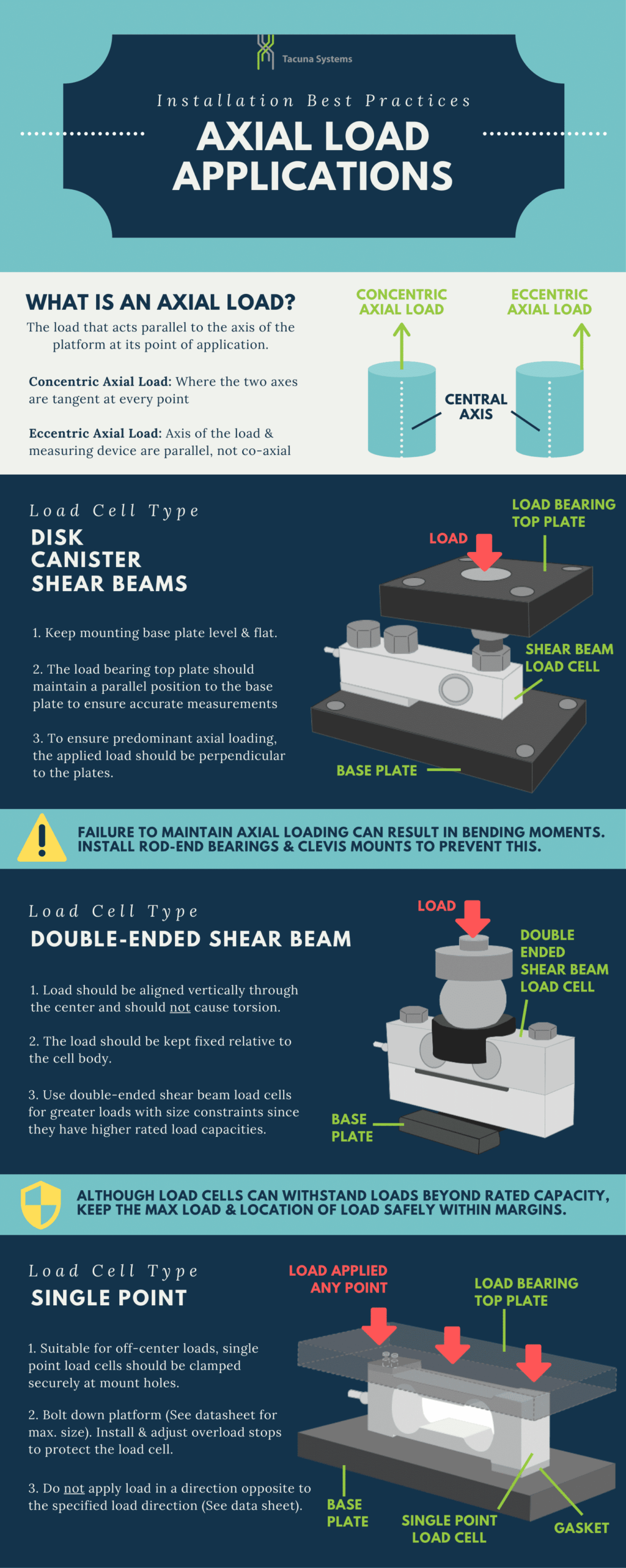
In addition to environmental factors, the measurement structure design must ensure the load path is axial. The load path is the direction the measured force travels through the load cell’s sensing element. Axial loading means the load:
- is orthogonal to the load cell,
- is concentrated at the load point,
- has its center of gravity positioned directly over the load point.
Misaligned loads can happen in two ways:
- when the frame and mounts improperly guide the load; and
- when any attached structures (such as supports, safety cables, pipes, and hoses) create “force shunts.”
This FAQ explains the effect of improperly guided loads on the load cell reading. The remainder of this section addresses solutions for the two sources of misalignment.
(a) Correctly Distribute and Guide the Load Through the Loading Point
The most common reason for inaccurate load cell measurements is improper axial loading. Since loads can be compressive, tensile, or torsional, properly guiding the load direction depends on the application. Section 4 describes mounting best practices to mitigate improper loading.
How to Ensure Axial Loading in Compressive Load Applications
Place load cells at all corners of the supporting structure to maintain the full weight or load. (While some manufacturers recommend placing “dummy” cells on supports and deriving the total load, dummy cells can prevent proper calibration.) When using load cells under structural supports, always arrange them on a level plane perpendicular to the force flow, and spaced at equivalent angles and distances from the center of force.
For systems using shear beams, single-point (platform), canister, and disk load cells, keep the lower mount plate level and flat. The top plate that translates the load must be parallel to the bottom plate under all conditions. Equally importantly, the load path must be perpendicular to both plates. This will maintain axial loading.
Likewise, when using double-end shear beams, be extra careful to avoid non-axial loads that cause shifting, twisting, or torsion. Since these load cells are practical in very high-capacity applications where size constraints exist, this issue is common. (Note that double-ended shear beams have higher load ratings than single-end shear beams, and are less bulky than equivalently rated canister load cells.)
How to Properly Align Tension and Suspension Applications
For tension applications such as pulleys, hoists, or cranes, and forklifts, fewer suspended supports will deliver more accurate results. Design suspension systems with adjustable linkages to distribute loads equally among load cells.
S-beam load cells can be used in both tension and compression. They are susceptible to large bending moments. As described in Section 4, install rod-end bearings and clevis mounts to prevent this. Also, since the internal strain gauge usually sits on a specific end of S-beam load cells; take particular notice of its correct orientation relative to the mounts and load.
(b) Avoid Force Shunts Through Attached Fixtures
A force shunt is any device or path through which a portion of the force flow or load is diverted. (For a more in-depth explanation of force shunts, see Measuring Forces in the Force Shunt.)
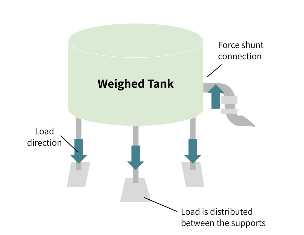
If the measured vessel has process connections such as piping or ducts, these should remain flexible to limit force shunting. (See Figure 1.) Small-diameter piping, or long segments without significant supporting structures, can also cause significant force shunting. If possible, use larger diameter connections. Connect piping with hoses or accordion tubing for best results.
Ladders, pipes, rods, and catwalks can all improperly load, or shunt, a portion of the measured structure. Remove these when measuring or compensate for the errors they introduce to the output measurement.
Despite these recommendations, safety is of the highest priority. Therefore, use safety features even if they create force shunts. Always deploy proper structural backup when a failure in the measuring structure could cause injury. For example, if a load pin could fail in a suspension application, use backup cables or stops to limit displacement that could harm equipment or operators. Again, choose flexible over rigid safety structures to help reduce force shunts while maintaining high levels of safety for operators.
3) Choose Load Cells Designed for the System’s Ambient Conditions
Every load cell will perform differently depending on the environment. Before building the measuring system, planners should do a thorough analysis of all the environmental factors that may be present, not just for the structure (as discussed in Section 1) but for the load cell choice as well. If the load cell application is not in a controlled environment, choose sensors with high IP ratings or other protections. Exposure to debris buildup, temperature, wind, precipitation, ice, sunlight, humidity, other electrical systems, and ground conditions all affect the load cell choice.
(a) Temperature
If ambient temperatures fluctuate, use temperature-compensated load cells. The load cell’s data sheet should indicate this. Uncompensated devices will be highly inaccurate at extreme temperatures. Therefore, if non-temperature-compensated load cells are part of your structure, shield them from radiant heat and cooling systems.
(b) Moisture
If the operating environment includes moisture or precipitation, check for an IP rating greater than IP65 (IP67 or more for forceful spraying) on the manufacturer’s spec sheet. Moisture can cause electrical shorts, which can, in turn, cause measurement errors and damage to a load cell not rated for these environments.
Take precautions to avoid corrosion of both the load cell device and the mount, and inspect both frequently for cracks and pitting. Use non-corrosive metals such as stainless steel.
(c) Electrical and Magnetic Fields
As mentioned before, stray electrical currents can interfere with load cell readings and cause damage to the device. Properly cover and secure all wiring and lighting. Ground the load cell fixture to the specifications outlined by the manufacturer. Again, avoid welding near load cells since any generated stray currents can significantly damage components.
Since magnetic and electrical fields can interfere with the weighing system’s signaling, place the load cell, connection cabling, and electronics in a shielded housing.
4) Factor In Electronics When the Frame’s Mechanical Design Can’t Compensate For All Unwanted Forces
Some installations cannot eliminate vibration, side loading, or torsional inputs entirely. In these cases:
- Apply low-pass digital filtering and signal averaging to mitigate vibration.
- Use the maximum filtering possible that still maintains the required measurement response time for the application.
- Select load cells designed to compensate for side loading or torsion when those forces cannot be removed mechanically. (See “Cancelling Unwanted Strain Components” In the article The Versatile Strain Gauge Load Cell.)
5) Correctly Build the Measurement Structure
After system design is complete, project execution determines performance. Mechanical installation errors are one of the most common causes of load cell inaccuracy and premature failure.
The following practices are critical.
(a) Weld Structural Components Before Installing Load Cells
Again, avoid welding the frame, fixture, or mounts in the presence of installed load cells. If welding or fabrication is required after load cell mounting, disconnect and protect all load cells. If electrical continuity must be maintained in these cases, use a temporary load cell simulator or weld shunt to prevent weld current from damaging the strain gauges.
Avoid welding the frame, fixture, or mounts in the presence of installed load cells. Stray currents from welding can damage these sensitive components. If welding or fabrication is required after load cell mounting, disconnect and protect all load cells. If electrical continuity must be maintained in these cases, use a temporary load cell simulator or weld shunt to prevent weld current from damaging the strain gauges.
(b) Use Rigid Mounting Plates with Tight Tolerances
The load cell mount’s surface and structure are critical for accurate measurement. When installing mounts, surfaces should always be clean, even (free of pits and burrs), and level.
Mount load cells to sturdy, rigid plates that are securely attached to the supporting structure. The plates must not flex under load. All applied force should transfer directly through the load cell into the structure without distortion.
Drill and tap mounting holes according to the manufacturer’s installation drawing. Maintain tight machining tolerances. Loose tolerances introduce unwanted stresses and can distort strain readings. For single-point load cells, the load must remain within the rated loading area. Design top plates and scale platforms accordingly.
(c) Use Mounting Accessories to Control Side Loads and Misalignment
If overload is possible from shock loading, impact, or wind loading, install mechanical load stops to protect load cells.
Also consider dimensional changes at full rated capacity. Load cells deflect under load. Verify that sufficient clearances remain at maximum load to prevent binding or unintended contact.
(d) Use Mounting Accessories to Control Side Loads and Misalignment
As stated before, measured loads must align with the load cell’s specified axis. When alignment cannot be guaranteed, mounting accessories are required.
- Rod ends and clevis assemblies reduce bending moments in tension applications. (Figure 2)
- Lateral stops limit horizontal movement caused by thermal expansion or shifting material loads (common in hoppers and tanks).
- Self-checking mounts automatically re-center structures after movement.
- Elastomeric bearings reduce heat transfer between tanks and load cells in tank weighing systems.
These accessories should manage unavoidable mechanical variables, not compensate for poor frame design.
(e) Choose the Right Hardware
Since mounting hardware (bolts, plates) is part of the load path, it must also meet the application’s reliability requirements. Shortcuts can be costly in the long term.
- Use only manufacturer-supplied or approved hardware.
- Ensure full thread compatibility.
- Fully engage all threaded fasteners.
- Tighten to specified torque values; do not over-tighten.
Each mounting plate must provide sufficient thread engagement. Plates that are too thin compromise joint strength.
Evaluate whether standard hardware is adequate for the application. If there is risk of yielding, shear failure, or fatigue, upgrade the hardware. The bolts must not be the weak point in the load path.
Before placing the system into service:
- Apply proper bolt preload.
- Maintain this preload while securing all hardware.
- Use jam nuts or locking features to prevent loosening.
If preload is insufficient or lost, joint separation and fatigue failure can occur.
Once again, add hardware that prevents suspended systems from rotating. Rotation can reduce preload and loosen fasteners, leading to joint failure.
(f) Maintain Cabling Integrity
Finally, ensure that all cables are supported to avoid crimping or stress at connection points with the load cell, junction box, or other electronics. Maintain all cable lengths. Cut or crimped cables alter resistances, which will change output readings.
Conclusion
As this article demonstrates, proper planning and execution of a measuring system’s installation are critical for its accuracy. Proper installation affects the mechanical load path, axial alignment, environmental performance, and the electrical measurement signal. Each system is unique and often has specific considerations to ensure it performs reliably even in extreme loading or environmental conditions.
Tacuna Systems engineers are always available to answer your installation or application questions regarding our load cell products.
References
- Measurement and Instrumentation Principles, 3rd Edition, Alan S. Morris
- Introduction to Instrumentation and Measurements, 3rd Edition, Robert B. Northrop
- Elements of Electronic Instrumentation and Measurements, Joseph J. Carr