
When your application uses multiple load cells, like a truck scale or a large tank, a junction box merges those individual signals into a single, accurate reading. These multiple load cell devices are typically arranged symmetrically around the corners of the measurement platform, distributing the weight over a wider physical area. Measurement accuracy that is insensitive to the position of the weight on the scale platform requires a process called “load cell trimming.” This process equalizes the inputs from the multiple load cells into a single, accurate output. This article explains the two trimming methods and the science behind them. For practical examples of junction box applications, see Research With Load Cells: Effects of Military Load Carriage on Ground Reaction Forces or Giving a crap: How a Simple Toilet and Load Cells are Tackling Global Ills in our “Featured Customer Projects” section of our Knowledge Base.
Key Takeaways
- Precision Through Trimming: Trimming equalizes individual load cell inputs, ensuring your weighing system remains insensitive to eccentric loading (off-center placement).
- Essential Scenarios: Without proper trimming, asymmetrical loads or mismatched sensors will produce unreliable data, which is unacceptable for “Legal-for-Trade“ compliance.
- The Safety Factor ($N$): When selecting test weights, always ensure the load does not exceed the rated capacity of an individual cell ($Scale\ Capacity \div N$) to prevent overload in individual cells.
- Method Choice: Choose Signal Trimming for superior stability and easier troubleshooting, or Excitation Trimming for high-precision control of the supply voltage.
- Procedure Logic: Both individual and sectional trimming rely on a “center-reference” method, matching corner outputs to a centered weight using the junction box’s internal potentiometers.
Weigh Systems That Require Load Cell Trimming
In multi-cell weigh systems, load cells or sensors are wired to the junction box in parallel for instantaneous data summing. However, this “raw” summed data is rarely accurate, especially when the load is eccentric. The trimming process resolves this issue by accounting for physical and electrical variances.
Trimming is essential in the following scenarios:
- Handling Asymmetrical Loads: Trimming ensures measurements remain accurate regardless of object placement or variable centers of gravity, such as with poured gravel or stacked packages.
- Compensating for Unequal Sensors: If a system’s geometry or maintenance prevents the use of identical cells at every corner, those cells must be trimmed before the system is calibrated.
- Meeting “Legal-for-Trade” Standards: For commercial scales like those found in airports or grocery stores, trimming reduces inaccuracies to meet legal requirements for customer transactions.

Trimming can be performed on each individual load cell in the weigh system, or in “sections.” The former is best for typical, four-corner scales, whereas the latter makes large-scale measuring system trimming more efficient. Below, we provide a step-by-step guide for each method.
Comparing Excitation vs. Signal Trimming Methods
There are two main types of load cell trimming: excitation trimming and signal trimming. This section explains the differences, electronically, and when to use each.
Excitation Trimming: What It Is and When It Is Ideal
Excitation trimming works by adjusting the “input” side of the load cell. As described in our load cell 101 article, the strain gauges within a transducer require a stable excitation voltage or current to function. By adding a series resistor known as a trimmer potentiometer (or “trim pot”), you can manually reduce the excitation voltage reaching each load cell, individually (see Figure 3).
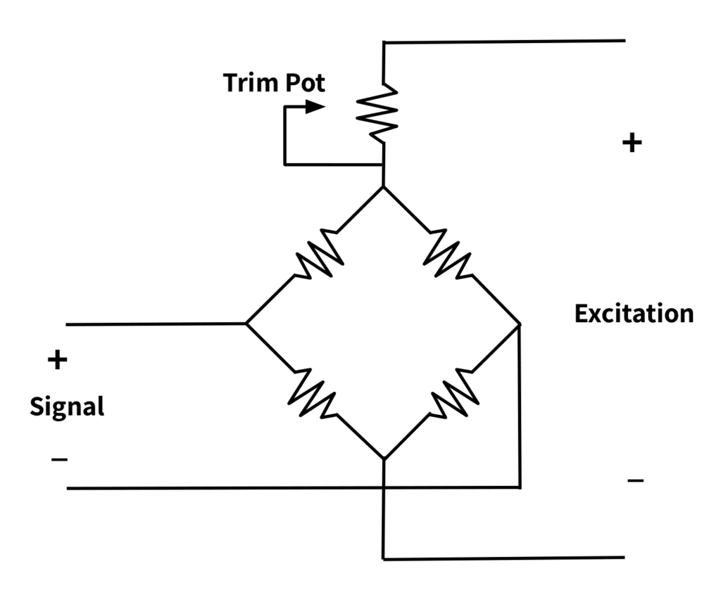
The Process: During excitation trimming, we place a known fixed weight on each load cell and adjust its output individually until the indicated readings for all of them are equal. When the trim pot resistance is adjusted, the excitation supply to that individual load cell increases or decreases. This in turn tunes the indicated weight.
The Outcome: When trimming is complete, the individual load cell with the lowest signal output receives the full excitation. The remaining load cells receive proportionally smaller excitation. This ensures the total load measurement is equivalent for all load cells in the system.
The Practical Application: Excitation trimming is ideal for high-precision applications needing compensation for slight variances in the measurement output directly at the power source.
Signal Trimming: How It Differs From Excitation Trimming and When It Is Better
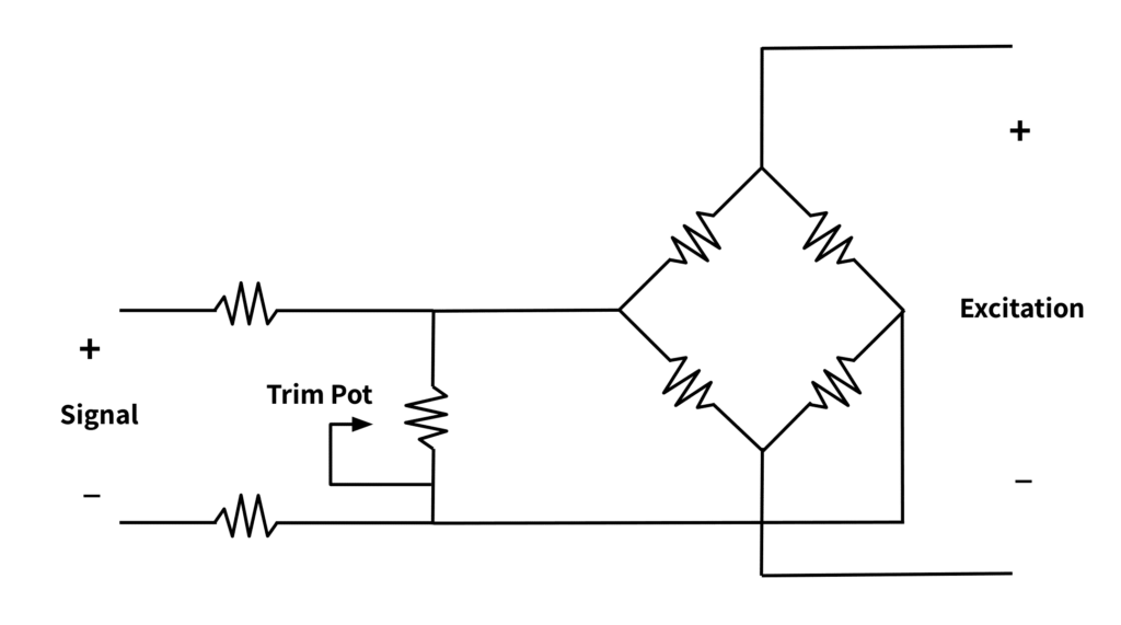
Signal trimming is the opposite of excitation trimming in that it adjusts the output signal.
The Process: This method places isolation resistors in parallel between the +/- output terminals of each load cell. These parallel resistors create a path for the load cell signal to “leak” before it reaches the junction box. A connected trim pot adjusts the individual load cell signals, as seen in Figure 4.
The Outcome: The resistors do not fully isolate the individual load cells from each other. However, they provide enough separation to prevent individual load cell measurements from interfering with each other.
The Practical Application: This trimming method is easier for troubleshooting errors and faults. Also, it is less susceptible to temperature changes or vibrations. This form of trimming is compatible with most load cell indicators (displays) and works with limited or gated power supplies. Furthermore, since this approach tunes each load cell’s reading to a standard value, it guarantees that the corner adjustment can remain the same even if you replace the load cell.
The Step-by-Step Procedure for Individual Load Cell Trimming
While selecting and mounting high-quality load cells is foundational, the trimming process is what actually synchronizes them into a single high-precision system. For added clarity, we have divided the process into two: preparation steps and trimming steps. Before you begin, ensure you have a flat-head screwdriver for the potentiometers and a high-accuracy multimeter for resistance verification.
Pre-Trimming Preparation and Calibration Steps
To achieve the greatest weigh system accuracy, before trimming, follow the steps below.
- Verify Potentiometer Resistance: Each individual potentiometer is factory-set to 5 Ω with a maximum capacity of 10 Ω. Use the multi-meter to verify that each potentiometer’s resistance is 5 Ω. If the resistance varies, turn the adjustment knob counterclockwise to increase, and clockwise to decrease.
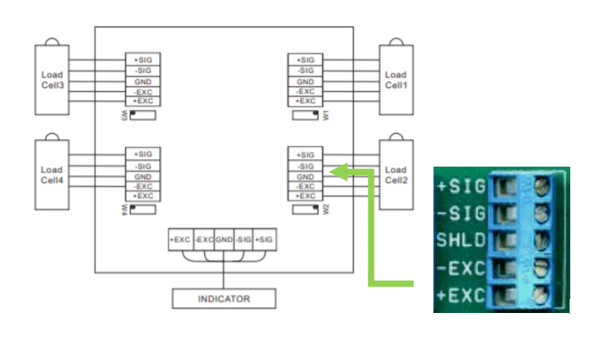
- Establish Connections: Connect each load cell’s cable and the scale’s digital indicator cable to the correct junction box terminals, following the manufacturer’s wiring diagram. Set the junction box’s internal switches to ON for each load cell.
- Zero the System: Before placing any test weights on the scale platform, zero the indicator.
The Corner-to-Center Trimming Procedure
This process uses a “center-reference” method to equalize the output of each corner sensor.
- Record Baseline Weights: Place a test weight on a single corner and record the reading. Move the weight to the center of the platform and record that value as your reference point. Repeat both steps for every corner. Note that test weight sizes depend on how many load cells are in the measurement system. If the system has N load cells, choose a weight that is no more than (scale rated capacity) \(\div \) N to avoid exceeding each individual load cell’s rated capacity.
- Use Potentiometers to Equalize Readings: Identify the corner with the largest deviation from the center-reference reading. Adjust its corresponding potentiometer until the corner reading matches the center reading. Note that for the junction boxes in our catalog, turning the knob counterclockwise increases the value (+), while turning it clockwise decreases it (-). This adjustment is the “trimming”.
- Verify and Repeat: Repeat Step 5 with each load cell corner, adjusting their potentiometers to equalize their values to the center measurement within the required tolerance. Check multiple times to ensure repeatability.
- Environmental Sealing: After completing these steps, replace the manufacturer’s chassis cover properly to prevent damage from moisture or debris.
Advanced Calibration: The Steps for Trimming Large Systems by Sections
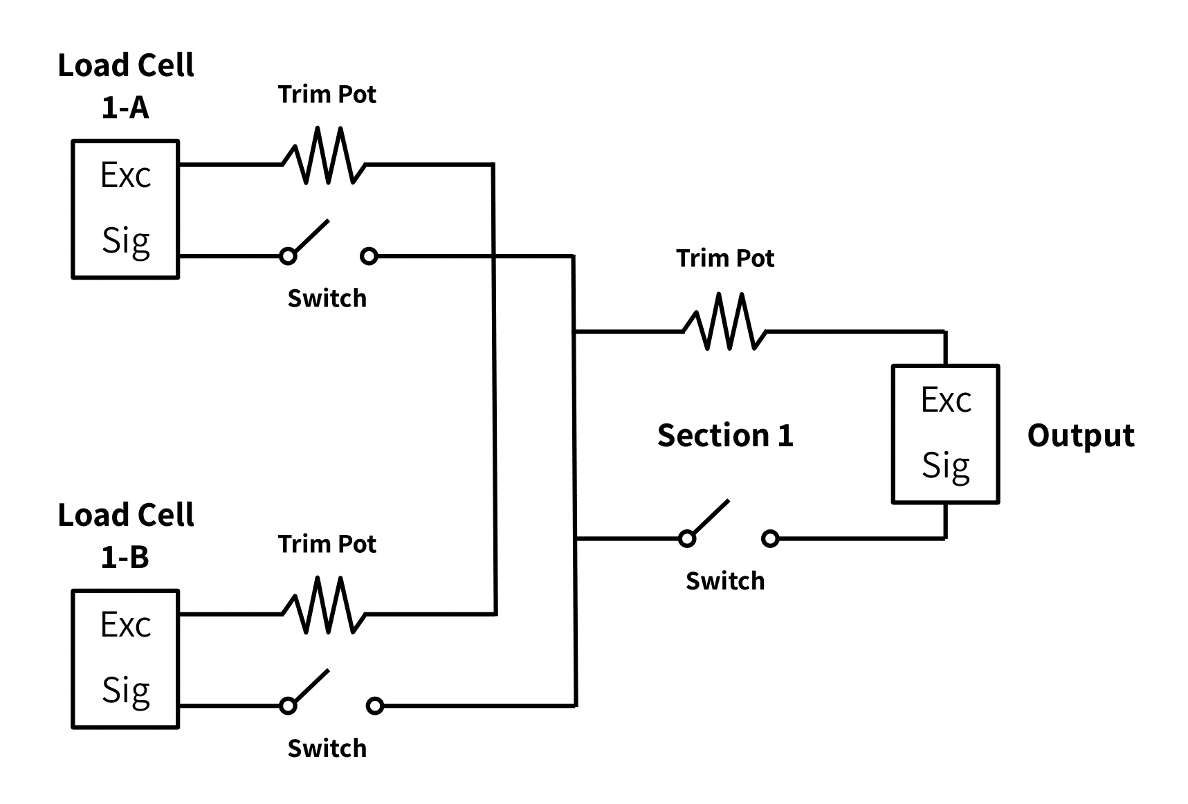
For systems with an even number of sensors, such as truck scales or long heavy-duty platforms, trimming individual cells can be inefficient. In these cases, we use Sectional Trimming to balance pairs of load cells across the scale’s width before equalizing the entire length of the system. The steps are as follows (refer to Figure 6).
- Initialize Hardware: Again, ensure that the resistance of each load cell’s potentiometer is correct, adjusting the pots as needed. Connect each load cell and scale display to the appropriate junction box terminals.
- Isolate the First Section: While each individual load cell has a corresponding dipswitch within the junction box, each pair or section also has a switch. The OFF switch will disable the section, while the ON setting will enable the section to measure. Enable Section 1, then enable “Load Cell 1-A.” Disable all other load cells. Place the test weight over Load Cell 1-A, and then over the center of the platform. Record the indicated weights.
- Balance the Pair: Next, enable “Load Cell 1-B,” disable the rest, and record the same two data points (corner vs. center).
- Equalize the Section: Compare the corner readings of cells 1-A and 1-B to their respective center-reference values. Identify and start with the cell that has the lowest indication relative to the center. Turn the corresponding potentiometer to adjust the cell’s output until it matches the center-reference reading. If a corner reading is higher than the center, turn the trim pot clockwise to decrease it; if it is lower, turn it counterclockwise to increase it.
- Calibrate the Entire Length: Repeat steps 1-4 for the remaining load cell pairs (sections). Once this is complete, enable one full section at a time (both load cells) at the junction box. Zero the indicator and place the test weight over the enabled section, take a reading, then place the weight over the platform’s center point and take a reading. Adjust that section’s potentiometer to trim it to that of the centered measurement.
- Final Verification: Repeat step 5 for all sections until the readings are within the necessary tolerance and are repeatable. Replace the scale cover properly before operation to prevent intrusion.
A Comparison of Junction Boxes
This section describes Tacuna’s product offering of load cell junction boxes.
| Product | # of Cells Summed | Type of Trim | Chassis | Standard Features | Variations |
| ANYLOAD J04EA-16 J04SA-16 J-BOX | 2 – 4 | Excitation: 350-Ω LC: 2.3% trim 700-Ω LC: 1.3% trim 1000-Ω: 1% Signal: 350-Ω LC: 3.6% trim 700-Ω LC: 6.3% trim 1000-Ω: 7% | Cast aluminum; IP67 | Pre-installed breather to prevent damage | Motherboard only option |
| ANYLOAD J04ES J04SS | 2 – 4 | Excitation and Signal; same limits as above | Stainless steel; IP65 | Lightning-protected electronics (“-II” model number extension) Motherboard only option for base and “-II” models | Lightning-protected electronics (“-II” model number extension) Expansion port to connect with other boxes plus lightning-protected chassis (“-E” extension) Smaller enclosure (“-FS” extension) Motherboard only option for base, “-II” and “-E” models |
| ANYLOAD J04SP | 2 – 4 | Signal Only: 350-Ω LC: 3.6% trim 700-Ω LC: 6.3% trim 1000-Ω: 8% | Fiberglass-reinforced polyester; IP67 | Gore Breather Vent Lightning protected electronics Expansion port to connect with other boxes | |
| ANYLOAD J06ES J06SS | 2 – 6 | Excitation and Signal; same limits as ANYLOAD J04EA-16 | Stainless steel; IP65 | Accommodates parallel load cell connections Independently adjustable potentiometers | Lightning protected electronics (“-II” model number extension) Motherboard only option for base and “-II” models |
| ANYLOAD J06S-E-21-MB | 2 – 6 | Signal Only: 350-Ω LC: 3.6% trim 700-Ω LC: 6.3% trim 1000-Ω: 8% | None (board only); IP67 (conformal coated board) | Lightning protected electronics Expansion port | |
| ANYLOAD J08ES J08SS | 2 – 8 | Excitation and Signal; same limits as ANYLOAD J04EA-16 | Stainless steel; IP65 | Independently adjustable potentiometers | Independently adjustable resistors |
| ANYLOAD J08SP | 2 – 8 | Signal Only: 350-Ω LC: 3.6% trim 700-Ω LC: 6.3% trim 1000-Ω: 7% | Fiberglass-reinforced polyester; IP67 | Gore Breather Vent Lightning protected electronics Expansion port to connect with other boxes | |
| ANYLOAD J12ES J12SS | 2 – 12 | Excitation and Signal; same limits as ANYLOAD J04EA-16 | Stainless steel; IP65 | Independently adjustable potentiometers | Lightning protected electronics (“-II” model number extension) Motherboard only option for base and “-II” models |
Conclusion
Large-scale and complex weighing systems require the use of multiple load cell devices to produce accurate measurements. Load cell summing and junction boxes properly combine their multiple signals into a useful digital output to display, store, or control complex systems.
To ensure the quality of load cell measurement data delivered to operators, the individual load cells must be properly trimmed. The trimming process equalizes the output from multiple individual load cells into a single, accurate output. Load cell trimming guarantees the correct measurements, regardless of where the weight is on the scale. As always, for best results, follow the manufacturer’s installation instructions, and ensure that installers are properly trained.
If your application uses Tacuna Systems’ product line and you have any questions about the trimming process for your individual case, please contact Tacuna Systems customer service.
References
- ANYLOAD Junction Box Manual, Q-YZ Manual-JB-J12ES-V1.2, https://tacunasystems.com/documents/J12ES-J12SS-junction-box.pdf
- Measurement and Instrumentation in Engineering: Principles and Basic Laboratory Experiments,1st Edition, Francis S. Tse, Ivan E. Morse
- Resistor Guide, your guide to the world of resistors: Trimpots http://www.resistorguide.com/tag/trimpot/
- Load Cell and Weigh Module Handbook: A Comprehensive Guide to Load Cell Theory, Construction and Installation, Rice Lake Weighing Systems