
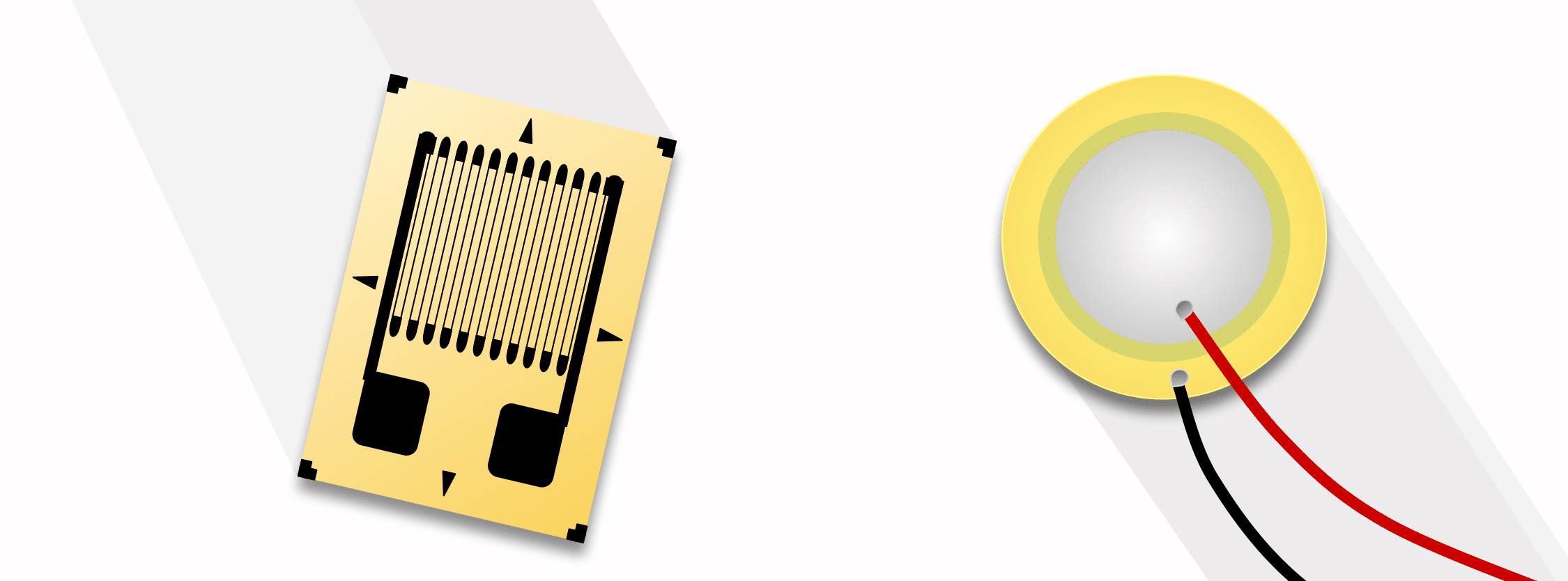
Many industries require weighing or measuring forces to perform their principal tasks. Strain gauges and piezoelectric sensors are two common transducer technologies that serve these industries.
Both transducers are widely used for almost the same applications. However, differences exist between these sensors. For one, performance factors differ such as resolution, accuracy, and susceptibility to environmental errors. Secondly, utilization factors such as ease of measurement, signal transmission, equipment interfaces, and physical characteristics distinguish them.
This article compares and contrasts these two types of sensors. It provides information to help system designers select components for a given application. Moreover, it aims to provide general information on how instrumentation and control systems use these devices.
Key Takeaways
- Strain gauges and piezoelectric sensors serve similar purposes but differ in characteristics such as sensitivity and form factor.
- Strain gauges convert force to electrical signals through elastic deformation, while piezoelectric sensors generate electric charge from pressure.
- Both systems have distinct materials, fabrication methods, and structural designs that affect their applications and effectiveness.
- Strain gauges excel in static measurements, whereas piezoelectric sensors are better for dynamic load applications.
- The choice between them depends on specific requirements, such as load range, environmental conditions, and sensitivity.
Principle of Operation
In this section we compare the science that enables each type of sensor to convert forces to electrical signals.
Strain Gauges
A strain gauge sensor transforms an applied force to an electrical signal through elastic deformation of the strain gauge. (See The Versatile Strain Gauge Load Cell for more information.) These forces can be static or dynamic in nature. Examples include weight, acceleration, and pressure. Internal to the gauge, this deformation in turn changes the dimensions of the strain gauge material. When the force is parallel to the gauge’s thin wiring and tensile, the wire lengthens and narrows (much like pulling a rubber band). This increases the resistance in the gauge. Likewise, a parallel compressive force widens and shortens the wire, decreasing resistance. The change in the material’s electrical resistance with either direction of force is proportional to the magnitude of the applied force.
The mathematical formula that relates the changes in dimension to change in resistance is:
\begin{align*}
\large{R}\pm \Delta R&=\rho \cdot \left ( \frac{L\pm \Delta L}{A \pm \Delta A} \right )\\ \\
\text{Where: }\\
R &=\text{ Resistance (in units of ohms, } \Omega \text{)} \\
\rho &=\text{ Resistivity (a constant in units of ohm-meter, }\Omega{m} \text{)} \\
L &= \text{ Length in meters (m)} \\
A &= \text{ Cross sectional areas in meters squared } (m^{2}) \\
\Delta A &= \text{ Change in cross sectional area in meters squared (}m ^2 \text{)} \\
\Delta {R} &= \text{ Change in resistance in ohms (} \Omega \text{)} \\
\Delta L &= \text{ Change in length in meters (}m \text{)} \\
\end{align*}
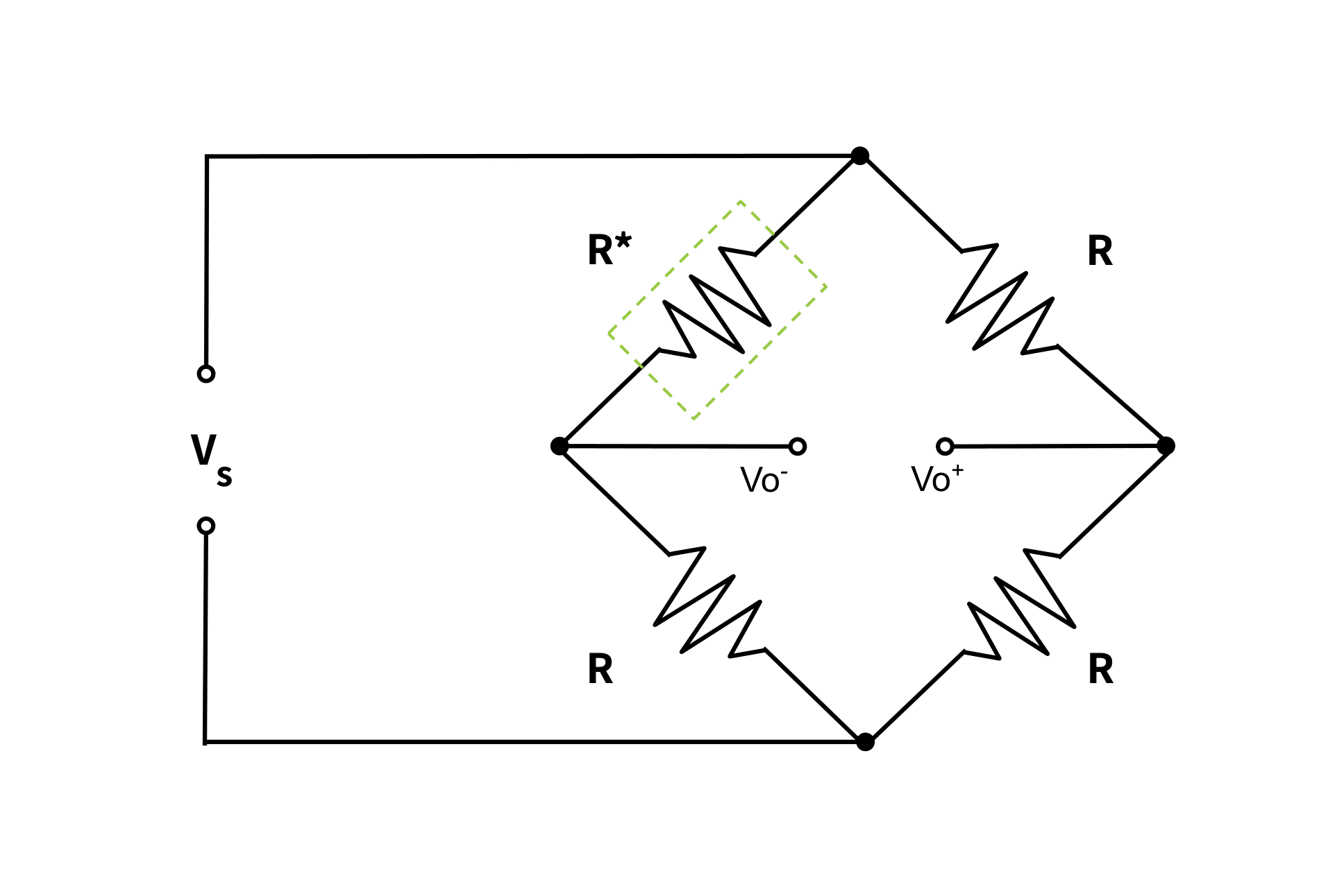
The output signal of the load cell is the voltage drop across this small change in resistance. This is possible due to the internal circuitry behind this delta, the Wheatstone bridge. See The Versatile Strain Gauge Load Cell for a more detailed explanation of the internal circuitry of this device. We give a simplified explanation here using one such bridge configuration: the Quarter Bridge.
Quarter-Bridge Configuration
The expression below Figure 1 shows the mathematical formula for a quarter-bridge configuration. Here dR is the change in resistance of the strain gauge:
\(\large V_{o}=\frac{V_{s}dR}{4R}\)
This analog output voltage is very small (mV). This makes it vulnerable to signal noise and interference. Also, the signal’s low magnitude is generally not great enough for a display to interpret. Therefore, the signal must undergo filtering and amplification through a signal conditioning circuit. For more detail on this topic, see Why Do I Need An Amplifier (and Other Signal Conditioners)?
Other Configurations
Half-bridge and full-bridge Wheatstone Bridge configurations also exist. They use two and four gauges respectively in the arms of the bridge circuit. Their multiple gauges compensate for, or eliminate strain effects other than the intended load strain. That is, the placement of additional gauges can cancel effects due to temperature, unwanted bending moments, and non-axial forces.
These configurations are covered in more detail in the articles, The Versatile Strain Gauge Load Cell and All About Electrical Connections Of Force Transducers.
Piezoelectric Sensor
A piezoelectric sensor makes use of a piezoelectric material. The available types of piezoelectric materials vary, but all transforms pressure into an electric charge. The magnitude of the applied load is proportional to, and therefore determined by, the quantity of this electric charge.
Also, a piezoelectric sensor can act as a piezoelectric actuator in a process called the reverse piezoelectric effect. This effect occurs when a supply of alternating voltage to the sensor makes the piezoelectric material start to vibrate.
Internal to the Sensor: Polarity of Piezoelectric Material
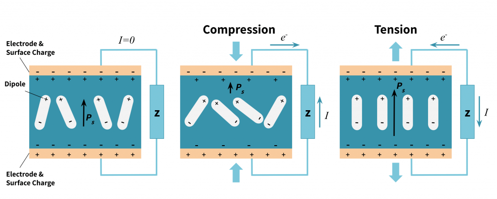
To illustrate the piezoelectric process, Figure 2 shows a manufactured crystal with polarity in steady state (leftmost drawing). The sensor’s piezoelectric material has dipoles (indicated by \(P_{s}\)with magnitude indicated by the length of the arrow) that create surface charges on the plates . Under a compressive force, this polarity weakens, the positive surface charge attracts electrons in the wire and the negative repels them, creating a current with the same polarity as the material’s dipole. Under a tensile force, the material deforms elastically and mechanically, strengthening its polarity. The surface charges are weaker than the material’s dipole, resulting in a current opposite the dipole’s orientation. This is a dynamic phenomenon. The difference in charges does not remain; therefore piezoelectric sensors work only with changes in pressure.
The mathematical formula for the amount of charge produced is:
\(q=a\cdot F\cdot K_{s}\)
where \(q\) is the electrical charge generated by force, \(F\) (in Newtons) applied across the faces of a piezoelectric device with a mechanical compliance of spring rate \(K_{s}\), in dimensions of \(mN^{-1}\) and a more complex material constant, \(a\), of dimensions \(C\) \(m^{-1}\).
Internal to the Sensor: Charge Amplifier
A charge amplifier then detects the electrical charge between the electrodes as either a charge source or a voltage source, depending on the amplifier design. Operational amplifiers (Op Amps) are preferable since they overcome the effects of stray cable, sensor, and amplifier capacitances.
There are several advantages to charge amplifiers. With modern microelectronic techniques, the charge amplifier can be embedded inside the transducer to shorten the gap between the electrode and the amplifier. Furthermore, charge amplifiers compensate for charge leakages common in piezoelectric material due to its large internal resistance. The ANYLOAD A2P-D2 Load Cell Amplifier, sold by Tacuna Systems is an example of a charge amplifier.
Material of Construction
This section explains the materials that make up each type of sensor. As explained above, sensor designs exploit the physical properties of these materials to convert forces to signals.
Strain Gauges
Strain gauge sensors use the strain gauge element as the underlying mechanism. The types of construction for these include thin-film, foil, and semiconductor strain gauges. A conductive material is bonded to a thin backing. This conductive material is usually copper-nickel, nickel chromium, platinum-tungsten alloys, and silicon for semiconductor gauges. The backing is non-conductive, and usually some form of polymer.
Piezoelectric sensors
Piezoelectric materials can be naturally occurring crystals like Rochelle salt and quartz. They can also be synthetic. Synthetic materials generally fall into two types: (1) crystalline such as Lithium Sulphate and Ammonium Di-Hydrogen phosphate, and (2) polarized ferroelectric ceramics such as Barium Titanate. The material chosen depends on the specific properties the application requires.
Method of Fabrication
This section compares the methods of construction of the two sensor types.
Strain Gauges
Bonded strain gauge fabrication involves attaching a length of a conductive strip to a thin backing. This is usually done through a process called micromachining. Micromachining usually follows the following steps:
- The conductive material is deposited onto a thin film,
- A “patterning” process arranges the conductor in a grid pattern, and then
- The fused materials are etched to remove the patterned parts, leaving the conductive wire.
The strain gauge is then carefully bonded to the sensor’s structural element surface with adhesives or other bonding agents. Proper bonding requires preparation of the surfaces. This involves the steps of cleaning, smoothing, roughening, and marking. The last fabrication step is then to hermetically seal the device to protect it against external mechanical and chemical damages.
Note that non-bonded strain gauges also exist, but their use is not as prevalent. The bonded strain gauge is preferable as it is more compact and easily embedded in the sensor’s structural element.
Piezoelectric Sensors
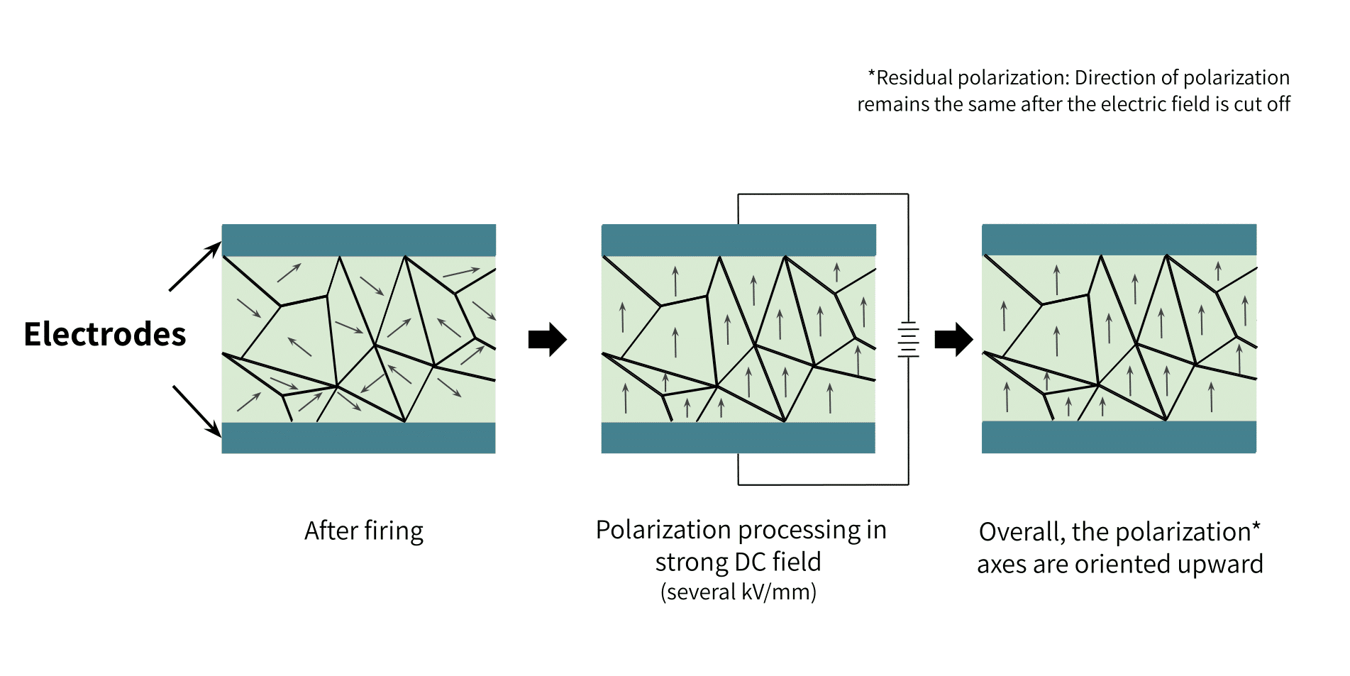
Synthetic piezoelectric materials like ferroelectric ceramics have randomly oriented internal electrical dipoles within their crystal structure. Therefore, fabricating sensors with these materials requires first polarizing them through the process of poling. Poling happens by first heating a powder material to a temperature level higher than the Curie point. The ferromagnetic properties of the crystal break down at this Curie point temperature. Then a strong DC electric field of several kV/mm is applied to the heated material; this field remains present while the material cools. After cooling and removing the field, the material maintains the dipole orientation it had under the field’s influence.
This fabrication process (Figure 3) establishes a strong piezoelectric property in the material.
The most important thing to consider during poling is the geometry of the crystal, especially when applying the electric field; this greatly affects the sensitivity of the material.
Natural piezoelectric materials like quartz simply need to be cut with fine precision tools to the application’s required dimensions. However, these natural single crystal materials have very bad crystal stability and a limited degree of freedom.
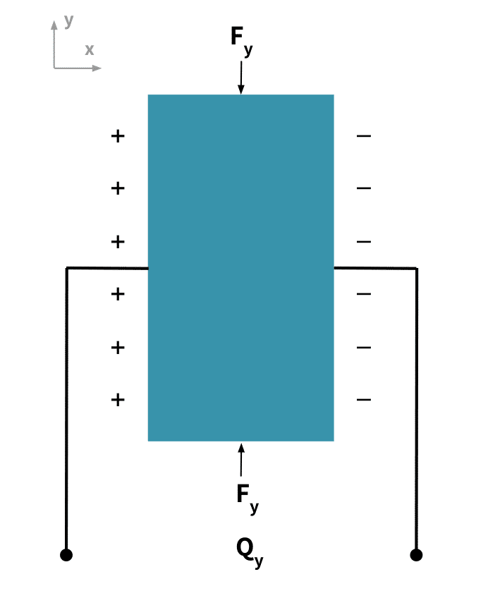
On the other hand, fabricated piezoelectric materials are more stable and can be created with properties tailored to specific applications. Moreover, the support substrate required by fabricated materials doubles as the outer electrode of the piezoelectric sensor. The substrate material’s orientation is such that the direction of the deforming stress is perpendicular to the polarity of the generated charges. Figure 4 below illustrates this point.
Sensor Characteristics
Both the piezoelectric sensor and the strain gauge have characteristics that make them ideal depending on the application. This section compares these criteria.
Geometric Shapes and Designs
Strain gauges most often appear in strain gauge load cells. These are durable metal structures that house a strain gauge. The position of the gauge in the structure allows it to capture strains at that location; engineers exploit this fact by creating these load cells in different geometric shapes with different load point characteristics. This diversity allows the load cells to adapt to the needs of different applications.
By convention, the geometric shape of the gauge’s structural housing unit gives the load cell it’s name. Some examples of so-named load cells are beam, S-shape, disc canister, or planar beam. Piezoelectric sensors also include housing designs in these shapes. Again, the geometry of the sensor depends on the application requirements.
Generally, piezoelectric sensor designs are more compact and are more rugged in construction than those of strain gauges. Their small size and excellent dynamic response makes them suitable for highly sensitive applications. They have wide uses from medical robotics to acoustics applications.
Both types of sensors can be used for multi-axial applications, and can support compression, shear, or bending stresses.
Other Specifications
Original equipment manufacturers provide datasheets with the electrical specifications of their transducers. This section explains some of these characteristics appearing on the datasheet. The values of these and other characteristics help designers choose the appropriate sensor for the application; likewise, they give the performance metrics technicians use to calibrate the resulting measurement system.
The Force Range:
This is the rated capacity (minimum to maximum accurately detectable force) in Newtons. The force range of the piezoelectric sensor is typically 5KN to 1MN. By contrast, the strain gauge sensor typically has a range of 5N to 40MN.
Loading Conditions:
Piezoelectric load cells can only support dynamic loads such as vibrations, accelerations, and dynamic pressure measurements; strain gauge load cells can support both static and dynamic loads.
Creep:
Strain gauge sensors have insignificant output drift when under a load for a long period of time; piezoelectric sensors have very large drift in output value, resulting in measurement errors for prolonged loading.
Stiffness:
Piezoelectric sensors have very high stiffness value. Strain gauges are more elastic and their durability depends on the load cell where they reside.
Resonant Frequency:
Unlike strain gauge transducers, piezoelectric sensors have a higher resonant frequency due to their stiffness. This value can be as high as 100,000Hz.
Sealing:
Both sensor types are designed to have very excellent seals, offering a high degree of protection and operational safety in harsh environments. The most common sealing technique is the hermetic seal.
Temperature Effects:
Both strain gauges and piezoelectric sensors are very sensitive to temperature changes. For both sensors, this affects their zero-balance, sensitivity, and linearity. Because of this, manufacturers use various compensation techniques: strain gauge sensors use self-temperature compensating gauges; piezoelectric sensors adjust for temperature effects with a charge amplifier.
Repeatability:
Both sensors can be designed to achieve excellent repeatability, or agreement between the results of successive measurements.
Linearity:
Strain gauge sensors have a lower linearity error in comparison to piezoelectric sensors.
Sensitivity:
This is the rate of change of the output as the desired input varies. The sensitivity of the piezoelectric sensor depends on the material used and its geometry; it is rated in Pico Coulombs per Newton (pC/N). A strain gauge transducer’s sensitivity depends on the excitation voltage and the rated capacity value; it is rated in millivolts per volts (mV/V).
Conclusion
Both strain gauge and piezoelectric force transducers are of undeniable importance to many force measurement applications. The choice between them depends on the application’s requirements. Manufacturers’ data sheets give the transducer’s input and output characteristics used in making the design choice.
Piezoelectric sensors offer excellent dynamic measurements, especially where compact size is a requirement. Strain gauge transducers are more common in heavy duty industrial applications, offering excellent dynamic and static load measurements. See Choosing the Right Load Cell for Your Job to learn which strain gauge load cell geometries are best suited for a particular application,
Other Resources:
- Force Measurement Glossary by Tacuna Systems.
- Force and Weight Measurement Resources
- An Overview of Load Cells by Tacuna Systems
- The Versatile Strain Gauge Load Cell
- Connecting a Force Sensor to a DAQ
- All About Electrical Connections Of Force Transducers
- How to Read a Load Cell Datasheet
References
- Piezoelectric Sensor, A Method for manufacturing a piezoelectric sensor and a medical implantable lead comprising such a sensor, US 8,626,313 B2
- Comparative look at strain gauge and piezoelectric sensors by JAC Chapman, Elexsys
- The Instrumentation Reference Book, Edited by Walt Boyes.
- Jayant Sirohi, Inderjit Chopra , “Fundamental Understanding of Piezoelectric Strain Sensors,” Journal of Intelligent Material Systems and Structures.