Piezoelectric force transducers serve an important purpose in force measurement. They are small in size and well-suited for applications requiring small components or the measurement of dynamic forces. This article explains concepts and processes related to the installation and mounting of piezoelectric force transducers.
Piezoelectric force transducers are essential tools for capturing precise, real-time force measurements in compact or high-speed applications. Their small size, sensitivity, and ability to measure dynamic forces make them indispensable in industries where these attributes matter most (such as robotics). In this article, we’ll explore the key principles behind these sensors and share practical insights for installing and mounting piezoelectric force transducers for optimal performance.
Key Takeaways
- Piezoelectric force transducers are vital for measuring dynamic forces in compact applications.
- Understanding how to install piezoelectric force sensors requires knowledge of safety guidelines and design details.
- Proper mounting considers accessibility, orientation, shape, resonant frequency, and damping for optimal performance.
- Charge amplifiers and appropriate cabling are critical components in piezoelectric sensor installations for accurate measurements.
- Calibration of the force measuring system is essential post-installation to ensure system accuracy.
What is a Piezoelectric Transducer?
A piezoelectric force transducer is a sensor that deforms under an applied force, then generates a proportional charge under this deformation. From this charge, the sensor then creates electrical signal at its output terminals.
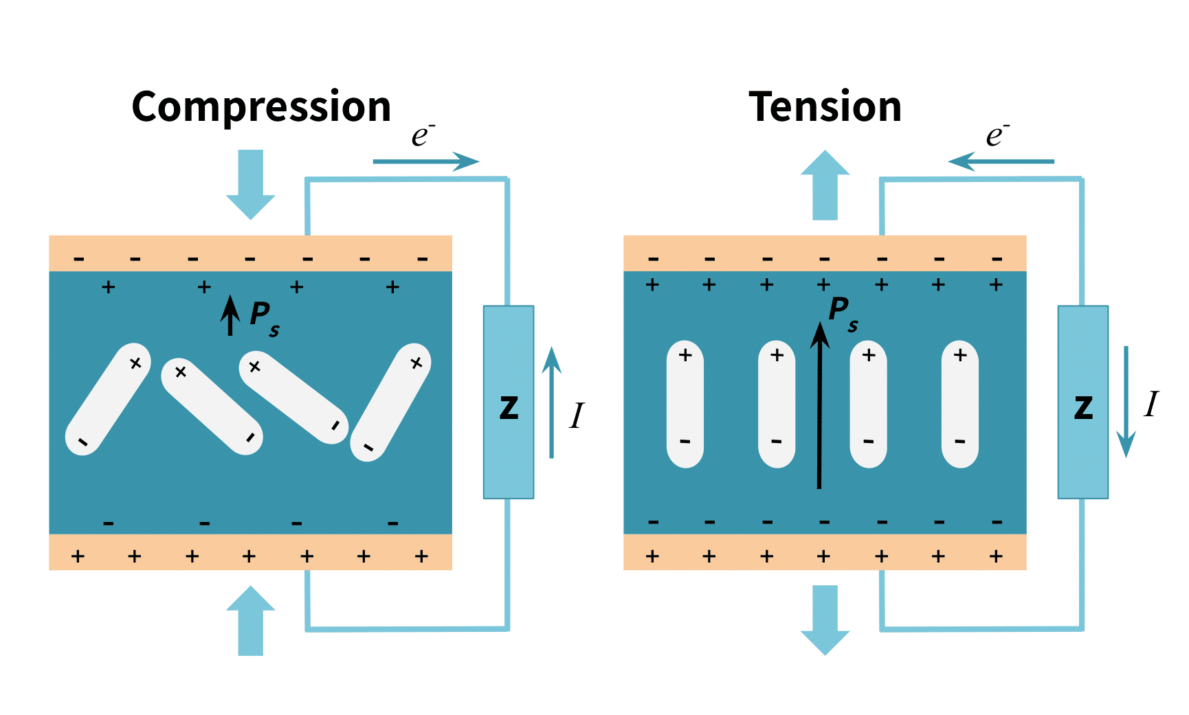
Piezoelectric transducers operate based on the piezoelectric effect. This effect happens when a polarized crystalline material undergoes stress or deformation. The stress then causes a shift in the material’s molecular geometry, creating (in a natural crystal) or altering (in a manufactured one) its polarity. It is similar to di-electricity, which occurs when a charge is produced from a shift of electrons in an insulator. Figure 1 below illustrates this effect. \(P_{s}\) indicates the polarity and the length of its vector indicates its strength. A decreased polarity creates a current in the direction of the crystal’s polarity, while an increased one creates an opposite current.
In an electrical schematic diagram, a piezoelectric force sensor appears as a charge source in series with a capacitance that has an internal resistance and inductance. Figure 2 below illustrates this.
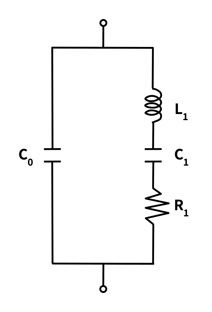
\(L_{1}\):
Serial Inductance
\(C_{1}\):
Serial Capacitance
\(R_{1}\):
Serial Resistance
\(C_{0}\):
Parallel Capacitance
\(C_{f}\):
Free Capacitance = \(C_{0}+ C_{1}\)
Furthermore, the mathematical formula that shows the relationship between the charge produced, the applied force, compliance, and the material constant appears below. The compliance of the material is the inverse of Young’s modulus.
\(q=a\cdot F\cdot K_{s}\)
Where \(q\) is the electrical charge generated by force, \(F\) (in Newtons) applied across the faces of a piezoelectric device with a mechanical compliance of spring rate \(K_{s}\) (\(mN^{-1}\) ) and a more complex material constant, \(a\) , of dimensions \(C\) \(m^{-1}\) .
The piezoelectric material lies along the transducer’s loading axis, that is, the imaginary line along the direction, and at the application point, of the measured force.
How Do I Install a Piezoelectric Sensor?
Installing a piezoelectric transducer requires a well-trained technician who understands the various standard safety requirements and guidelines.
In an industrial setting, personnel should follow the installation design details describing the location of installation for the transducer, the sealing of the transducer’s housing unit, the wiring diagrams, cable requirements, and grounding of the system. Also, installers should be able to perform both the pre-installation testing and post-installation loop testing.
Considerations for Mounting a Piezoelectric Force Transducer
Mounting the device at the intended location requires attention to these factors:
1) Accessibility:
The mounting position should be chosen such that the device is easily accessible to the authorized personnel for repairs and maintenance.
2) Orientation of the piezoelectric material:
As mentioned above, installation of the material inside the sensor must be such that the polarity runs along the loading axis.
3) The transducer’s geometric shape:
The shape of the transducer will affect the orientation of the underlying piezoelectric material, and therefore the orientation of the output electrodes that detect the output electric field. The transducer should be mounted so the position of its output electrodes is perpendicular to the direction of applied stress.
4) Resonant frequency:
The natural frequency of piezoelectric materials can be as high as 100,000Hz and they are not self-damping. If driving the transducer to this frequency level is unnecessary, then mounting measures should ensure the maximum frequency falls below it.
5) Damping:
Damping is necessary if the piezoelectric material typically operates in an environment with vibration, especially at its natural frequency. Mounts using spring elements can dampen by pre-compressing the transducer. This gives more support, better rigidity, and firmness under vibrations of different amplitudes. Damping also greatly improves linearity of the input/output curve.
6) Cabling:
The transducer’s electrode cables must have proper insulation and be short in length. Altering the cable length after installation changes the capacitance; therefore cutting or adding cabling requires knowledge of how to compensate for the new capacitance. Also during installation, any exposed cable should be kept clean and free of dirt, debris or even human contact. Coaxial cable is the recommended wire type for installing piezoelectric transducers.
7) Housing unit:
Once installed, the transducer is housed typically in a vacuum. This ensures the absence of air loading and proper damping, and seals against dust and dirt particles.
8) Signal conditioning peripherals:
These devices should be placed as close as possible to the transducer. This will reduce the distance of charge and signal transmission, which reduces unnecessary noise coupling and voltage drops.
9) Grounding and shielding:
This is a very important step during installation. The transducer requires a proper ground to protect the device. Shielding protects against electromagnetic interference, and the possibility of the reverse piezoelectric effect. This effect occurs when the material begins to vibrate at a certain frequency from exposure to an electrical time-varying signal such as an AC voltage.
Peizoelectric Sensor Installation Components
The important components for installing piezoelectric sensors are the transducer itself, the connecting cables, and the charge amplifier. The previous sections covered cabling considerations and the transducer’s operating principles. This section explains the remaining component, the charge amplifier.
The Charge Amplifier: Circuit Schematic
The charge amplifier is an electronic circuit that converts the charge output from the piezoelectric sensor to a voltage output. The design includes an operational amplifier with a high input impedance (usually a MOSFET input stage), a suitable frequency response, and a low output impedance. The charge amplifier also uses a feedback technique to provide gain adjustment and signal filtering.
Figure 3 below shows the schematic of the charge amplifier connected with the modeled cable and sensor.
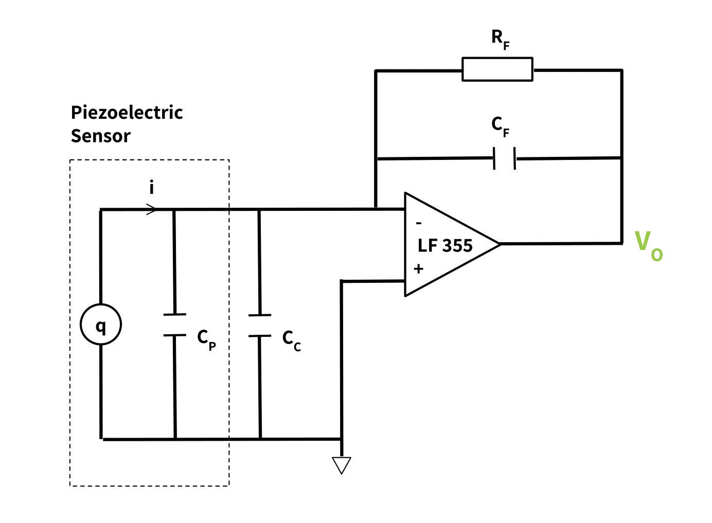
In the diagram, \(q\) is the charge source in parallel with the sensor capacitance \(C_{P}\) ; \(C_{c}\) is the cable capacitance which is also in parallel with the sensor parameters; \(C_{F}\) and \(R_{F}\) are the feedback capacitance and resistance respectively. Recall Figure 2 shows a resistance in series with this parallel capacitance \(C_{P}\) (labeled \(C_{1}\) in the previous figure). It is this resistance that causes charge leakage.
The Charge Amplifier: How its Design Affects Measurement Quality
This type of charge amplifier design ensures:
- A calibration factor fixed by the value of the feedback capacitance and resistance \(C_{F}\) and \(R_{F}\).
- An adjustable dynamic frequency range as the time constant (\(R_{F}\) * \(C_{F}\)), but only for dynamic loading. (It can be made large or small for low and high-frequency operations respectively.)
- Eliminated effects of stray capacitances from the connecting cables \(C_{c}\) and the sensor \(C_{P}\).
These three results give the piezoelectric transducer a high stability, wide dynamic range, good temperature stability, good linearity, and low hysteresis.
The output terminal of the charge amplifier can then connect to an analog-to-digital and signal processing component; or it can connect to a voltage meter.
The Piezoelectric Sensor Data Sheet: Important Specifications
A manufacturer’s datasheet for piezoelectric sensors should give its specifications as values for the following characteristics. They provide important data for the installation process.
- Relative Dielectric Constant: This quantifies displacement under a unit electric field and zero stress.
- Electromechanical Coupling Factor: This indicates the efficiency of the transducer. Efficiency is the relationship between the supplied electrical energy and the output mechanical energy of the material.
- The Piezoelectric Distortion Constant: This is the resulting distortion when an electric field of uniform strength is applied under zero stress.
- The Voltage Output Coefficient: This is the effective electric field strength under uniform stress but zero electrical displacements.
- Resonant Frequency: This is the natural frequency of vibration of the material.
- The Mechanical Quality Factor: This indicates the steepness of the response of the material to a mechanical vibration equal or close to its resonant frequency. Materials with high “Q” resonate at frequencies only close to their resonant frequency and with a high amplitude; meanwhile those with lower “Q” values resonate at a wider frequency bandwidth. In each case the resonant frequency is typically at the center of the response frequency band.
- Poisson’s Ratio: This is the ratio of the traverse strain to the axial strain when a constant stress is applied to the material.
- Curie Temperature: This gives the temperature at which the material loses its polarization and piezoelectric properties. At this temperature the once aligned dipoles arrange themselves randomly.
- The Compliance: This is also called the elasticity constant and it is the inverse of Young’s Modulus. That is, it is the ratio of strain (deformation of the material) to stress (applied force).
Conclusion
The piezoelectric force transducer is most suitable for dynamic measurements. Therefore it commonly appears in ultrasonic applications, shock measuring sensors, airbags, acceleration measurements, etc.. Its compact size makes it preferable for small systems.
A final point is that once mounting and installation is complete, the piezoelectric force measuring system should be calibrated. (See Calibrating the Force Measuring System.) Calibration simply involves comparing the reading of the piezoelectric transducer to that of a known standard. This will identify systematic errors and improve accuracy.
Other Resources:
- An Overview of Load Cells
- The Piezoelectric Effect and Its Applications
- Comparing Strain Gauges to Piezoelectric Sensors
- Load Cells and Force Sensors in Robotics
- Connecting a Force Sensor to a Data Acquisition Sensor DAQ
- Load Cell Mounting and Installation Best Practices