
Designing a precision measurement system relies on choices beyond the right load cell capacity. The engineer must also consider the system’s resolution, or the smallest change in weight it can reliably detect. This guide explains how to calculate the lowest measurable weight by balancing load cell specifications with the capabilities of your display, amplifier, and Analog-to-Digital Converter (ADC).
Key Takeaways
- The Smallest Certified Weight, \(v\): A load cell’s divisions \(n_{LC}\) determine its verification interval \(v\). This is the smallest weight increment the sensor is certified to measure accurately.
- The Gatekeeper Display: For a weight change to be shown, the scale display’s input sensitivity must be finer than the tiny voltage change produced by a single \(v\).
- The Digital Granularity Requirement: The modern rule of thumb is to encode the load cell output with a high bit-depth ADC (typically 24-bit). This provides the “digital headroom” to account for dead loads and ensures the display doesn’t “flicker” between increments.
- Consider Resolution vs. Accuracy: High resolution is only half the story; a displayed number is only reliable if the system’s accuracy is tighter than the smallest measurement increment.
- The True Measurement Floor is the Maximum Error: The ultimate smallest limit of a measurement is determined by the load cell’s combined error and repeatability. If these physical errors exceed the desired resolution, any measurement change smaller than these errors is effectively a guess.
The Most Important Data Sheet Specifications: Divisions and Full Scale Output
Every strain gauge load cell data sheet includes a critical specification: the number of divisions (\(n_{LC}\)). These divisions represent how many increments the full-scale output (FSO) can be split into. As we established in our guide to OIML Requirements (and NIST Requirements), these divisions determine the accuracy class. They also define the verification interval (\(v\)), or the Maximum Measuring Range divided by \(n_{LC}\). Figure 1 depicts the relationship between these concepts.
Figure 1: Terms Associated With Loads Applied to Load Cells, and Their Relationship
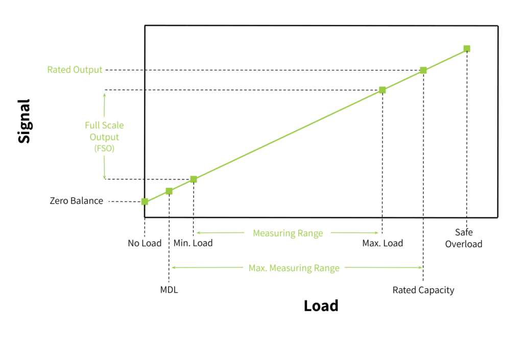
This verification interval is the smallest weight that the load cell alone is certified to measure accurately. (See this FAQ regarding verification interval vs smallest weight measurable.) However, once that load cell is part of an entire measurement system, the display resolution and amplifier become the new limiting factors.
The Scale Display’s Resolution: How it Affects Minimum Weight
A display’s input sensitivity is the smallest voltage change it can detect. Therefore, a weigh system will only be accurate if the voltage produced by the load cell’s smallest detectable weight increment is greater than the display’s sensitivity.
For example:
Assume you have a scale having an internal load cell with a 50lb capacity, an FSO of 1 mV/V, and a 10V excitation (\(V_{ex}\)). At maximum load, the output to the display is:
\(1mV/V \times 10V = 10mV\)
If this 50lb cell has 8,000 divisions, the verification interval weight, \(v\) is 0.1 oz \(0.00625\text{ lbs}\). To find the voltage at this weight \(X\), taking advantage of the linear relationship shown in Figure 1:
\begin{align*}
\frac{0.00625 \text{lbs}}{50 \text{lbs}} &= \frac{X mV}{10 mV}
\text{ therefore, }\\ \\
X &= 10 mV \times \frac{0.00625}{50} \\ \\
&= 0.00125 mV, \text{ or }1.25 \mu{V}
\end{align*}
This means the display’s input sensitivity must be smaller than \(1.25 \mu{V}\) for a weight of \(\frac{1}{10} oz\) to appear on its screen. Likewise, any weight with a tenth of an ounce fractional portion will round to the nearest display-detectable increment. Clearly, then, the lowest weight detectable by a load cell is not the only consideration in designing a weighing system.
Note that most displays can handle a small input signal such as the one in this example, since they generally have internal amplifiers. The next section explains the effects of amplifiers on the overall weighing system’s resolution. It also covers resolution issues associated with digital signal converters.
Signal Amplification and Digitization Also Affect Scale Resolution
Because a load cell outputs a signal in the millivolt \(mV\) range, it is incredibly faint and susceptible to interference. To be readable by a computer or display, it requires high-fidelity amplification and sometimes digital conversion. We will cover both here, but for more in-depth information, see Why Do I Need a Load Cell Amplifier and Other Signal Conditioners?
The Instrumentation Amplifier: Why it is Needed for Scale Resolution
The most common load cell output signal booster is the instrumentation amplifier. It serves two critical purposes:
- High Input Impedance: This ensures that the amplifier can receive the load cell’s output voltage without adding an electrical load on the sensor itself.
- Differential Amplification with Common Mode Rejection: Since a load cell’s output signal is the voltage difference between two wires (see the Wheatstone Bridge circuit), differential amplification has the desired effect of boosting this differential signal (the actual weight signal) while ignoring any electrical interference that hits both wires equally (the “common mode” signal).
Figure 2 shows a standard instrumentation amplifier circuit.
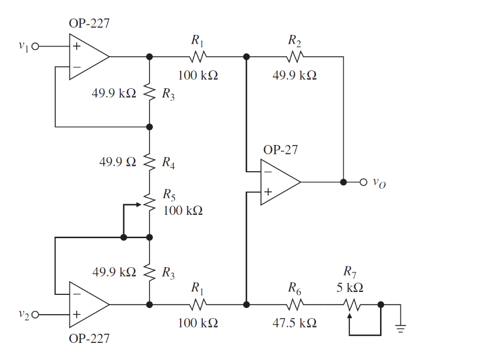
Figure 2: Instrumentation Amplifier
Beyond these, the instrumentation amplifier must meet several strict criteria:
- Low Drift & Low Offset: With time and varying temperatures, a signal at the “zero” point can slowly change, making a reading look non-zero even when no weight is applied.
- High Power Supply Rejection Ratio (PSRR): This ensures that tiny ripples in the amplifier power source aren’t misinterpreted as weight changes.
- Low Input Bias Current [2]: Ensures the amplifier doesn’t “contaminate” the load cell output signal with its own internal current, which avoids unwanted voltage drops across the sensor’s resistors.
Each of these mitigates factors that alter the tiny load cell output signal associated with the verification interval, \(v\). One can see how any signal alteration would make a small weight change measurement unreliable. So, an instrumentation amplifier with all these qualifications will produce a high enough signal-to-noise ratio for the ADC to digitize the true weight signal accurately.
Analog to Digital Conversion and its Effect on Resolution
To achieve a reliable resolution, the weigh system’s ADC must have a bit-depth significantly higher than the load cell’s number of divisions. While 3,000 divisions require about 12 bits (\(2^{12}\), or 4096 steps) of mathematical range, modern weighing systems use 24-bit ADCs (providing over 16 million internal counts).
This massive ADC resolution provides the necessary headroom to account for the scale’s Dead Load (the MDL, or weight of the platform) and Overload safety margins. (Again, refer to Figure 1 to see that these voltages exist outside the measurement range; a load cell’s divisions describe measurement increments only within that measurement range.)
More importantly, it provides thousands of internal steps for every single displayed increment, allowing the system to digitally filter out vibration and noise to produce a stable, non-flickering weight reading. Load cell indicator manufacturers generally give the ADC’s minimum number of bits required for stable readings.
Beyond Resolution: How Error Tolerances Affect Small Measurement Accuracy
The load cell’s divisions, along with the amplifier’s and display’s respective capabilities to detect a low signal clearly affect the weighing system’s resolution. However, the reliability of these measurements is only as good as the quality of the load cell itself. A few of its specifications tell us its error tolerances under certain ambient conditions. For applications requiring high accuracy, you will want these tolerances to be as low as possible. The reason for this is that the tolerances are given as a percentage of full-scale measurements (FSO). One can see how this value can be a large percentage of a small measurement increment. Likewise for high-accuracy applications, you will want a load cell with a higher level of sensitivity.
Figure 3 displays typical specifications found on a load cell data sheet. They are explained further in this section. More information appears in these articles: How to Read A Load Cell Datasheet and Load Cell Classes: NIST Requirements.
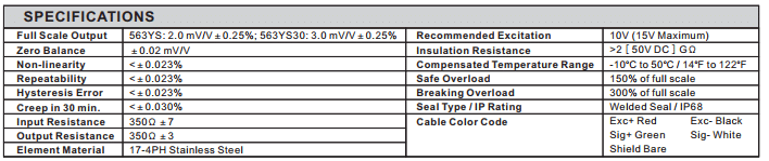
Figure 3: Specifications from a Load Cell Data Sheet
Maximum (or Combined) Error
The combined error or maximum possible error is the total measurement uncertainty created by the sum of non-linearity, hysteresis, and temperature effects, such as creep. It is important when considering accurate division measurements [3], since it is given as a percentage of the load cell FSO. This means the total error could be very high compared to a single increment of measurable weight.
For example, if a load cell has a combined error of \(0.03\%\) FSO, and your goal is to measure a \(1\text{ lb}\) increment on a \(1,000\text{ lb}\) scale, you have a problem:
\(1,000\text{ lbs} \times 0.0003 = \pm 0.3\text{ lbs}\)
In this scenario, the uncertainty is nearly a third of the smallest measurement. This makes the last digit on the display technically visible, but statistically unreliable.
The following definitions are important determinants of a load cell’s accuracy class. These definitions are provided from the Handbook of Electronic Weighting.
Non-Linearity
As Figure 1 suggests, the output voltage per input weight is linear in the load cell’s measurement range. In reality, this relationship is slightly curved. Non-linearity is the maximum deviation from this line. The smaller the non-linearity, the more accurate each measurement will be. Likewise, the more similar the output voltage will be for a 1g change near the scale’s zero as for a 1g change near rated capacity.
Hysteresis
This is the difference in output for the same weight depending on whether you are increasing the scale’s load or decreasing it. Hysteresis is caused, in part, by the ability of the spring element to return to its “zero” state in a given amount of time. If you weigh a small item after removing a very large weight, the metal might not have fully returned to its zero point, causing a false reading on the smaller measurement. Quality load cells have low hysteresis.
Creep
Creep is the change in the load cell output signal over time under a constant load and unchanging environmental conditions. If you leave a weight on the scale for 30 minutes, the molecular structure of the strain gauge and adhesive can “relax.” This can cause the weight reading to slowly drift.
Creep is problematic for lowest-weight measurements in applications like tank level monitoring, where weight sits for weeks at a time.
Repeatability
This is the maximum difference in the load cell’s output signal for repeated identical loads under identical environmental conditions. A small value depicts a high system accuracy and reliability.
For lowest-weight measurements, repeatability is the floor of confidence in measurement accuracy. For example, assume you place a 5g weight on a scale 5 times. The readings are: 5.0 g, 5.1 g, 4.9 g, 5.0 g, and 5.2 g. This means the repeatability error is 0.2 g. If you desire a resolution of 0.1 g, the repeatability error of this example scale is too great.
Temperature Effect on Output
Temperature changes alter the resistance of the gauges. Therefore, they can introduce errors that affect system accuracy. This is why load cell specification sheets give a compensated temperature range. Maintaining the weigh system’s operating environment within this ambient temperature range will ensure the load cell operates within its specified tolerances.
Summary
Finding the lowest weight a load cell can measure requires balancing the sensor’s certification with the system’s electronic and physical limits. While the verification interval \(v\) sets the target, the instrumentation amplifier and 24-bit ADC must provide a clean signal and digital headroom needed to display that weight without instability.
However, the final influencer is always accuracy. If the sum of the load cell’s combined errors and repeatability exceeds the displayed increment, you have resolution without reliability. For a measurement to be trusted, the sensor must be as precise as the electronics used to read it. This is especially important in Legal for Trade applications.
Note that even if the cell’s accuracy and precision are not great, it will still produce a measurement. This FAQ question and answer address this case. Since every application has different requirements, contact Tacuna Systems if you have any questions regarding whether the resolution and accuracy of your weighing system are sufficient for your objectives.
Sources
- Brusamarello, V., Machado de Brito, R., Muller, I., Pereira, C. E., “Load Cells in Force Sensing Analysis – Theory and a Novel Application”, ResearchGate, Jan. 2010.
- Franco, S. “Design with operational amplifiers and analog integrated circuits”. New York: McGraw-Hill. pp. 87, 2015
- K. Elis Nordon, “Handbook of Electronic Weighting”, Wiley-VCH, pp. 24-29, Jul. 1998.
- “Load Cell Accuracy in Relation to the Conditions of Use”, Technical Note VPGT-02, Jan. 8 2015. Retrieved from http://www.vishaypg.com/docs/11864/11864.pdf
- “Load Cell and Weight Module Handbook”, Rice Lake Weighing Systems, pp. 9-10, 2010
- “OIML Certificate of Conformity”, Number R60/2000-NL1-10.27 , Dec. 2010
- “R 60 OIML-CS rev.2”, NIST Handbook 44, pp. 1-4, Jan 5 2018.