
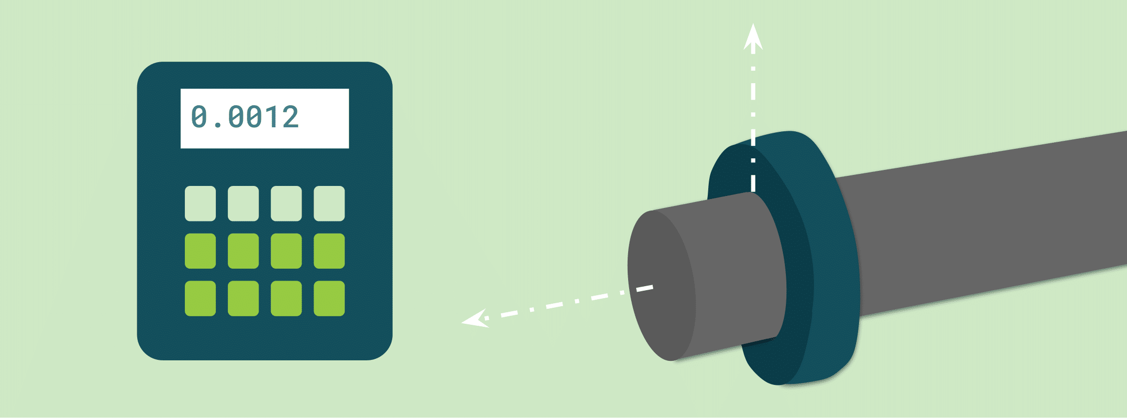
Accurately measuring axial thrust is an essential preventative maintenance step in rotating machinery (such as centrifugal pumps and turbines). Knowing forces and especially changes in the forces on rotating shafts can predict mechanical failures in bearings and seals and shaft deflections that could lead to catastrophic breakdowns. Here, we look at how axial thrust develops in centrifugal pumps. We follow it with a step-by-step approach to engineering a load cell-based thrust measurement system.
Key Takeaways
- Thrust Mechanics: Axial thrust in pumps results from fluid pressure differentials across the impeller shrouds, changes in fluid momentum, and dynamic unbalance over time.
- Sensor Requirements: Thrust measurement requires bidirectional load cells (supporting both tension and compression) sized for maximum expected dynamic forces and environmental factors.
- Test Stand Alignment: Thrust frames must maintain strict axial alignment with the shaft axis to prevent off-axis side loading errors.
- Signal Conditioning: High-speed filtering and instrumentation amplification are required to isolate true thrust forces from motor vibration and electrical noise.
Understanding Axial Thrust in Rotating Equipment
Axial thrust is the net force acting parallel to an object’s rotational axis. In turbomachinery, this force pushes or pulls the rotor shaft along its longitudinal axis toward or away from its housing.
Depending on system design, axial thrust can be tensile (pulling away from the mounting platform) or compressive (pushing toward the platform).
Axial Thrust Generation in Centrifugal Pumps
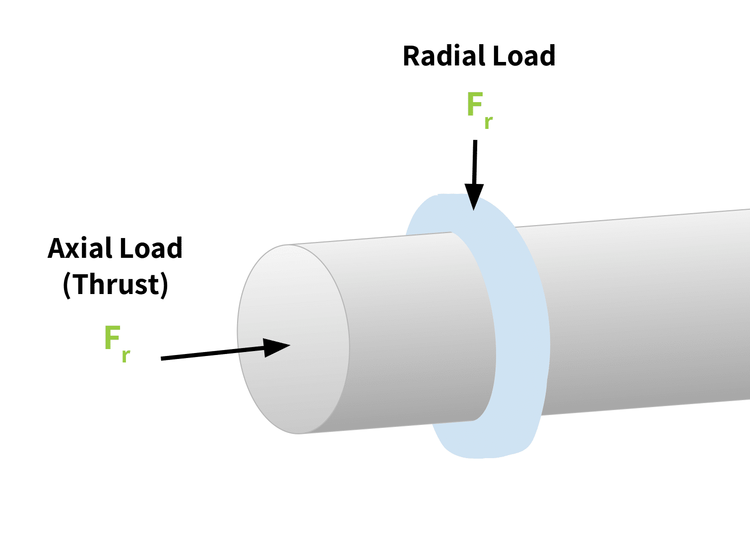
Centrifugal pumps convert motor rotational kinetic energy into hydrodynamic energy to transport fluids. During operation, radial forces act perpendicular to the shaft due to casing geometry, while axial forces act along the shaft centerline.
Components
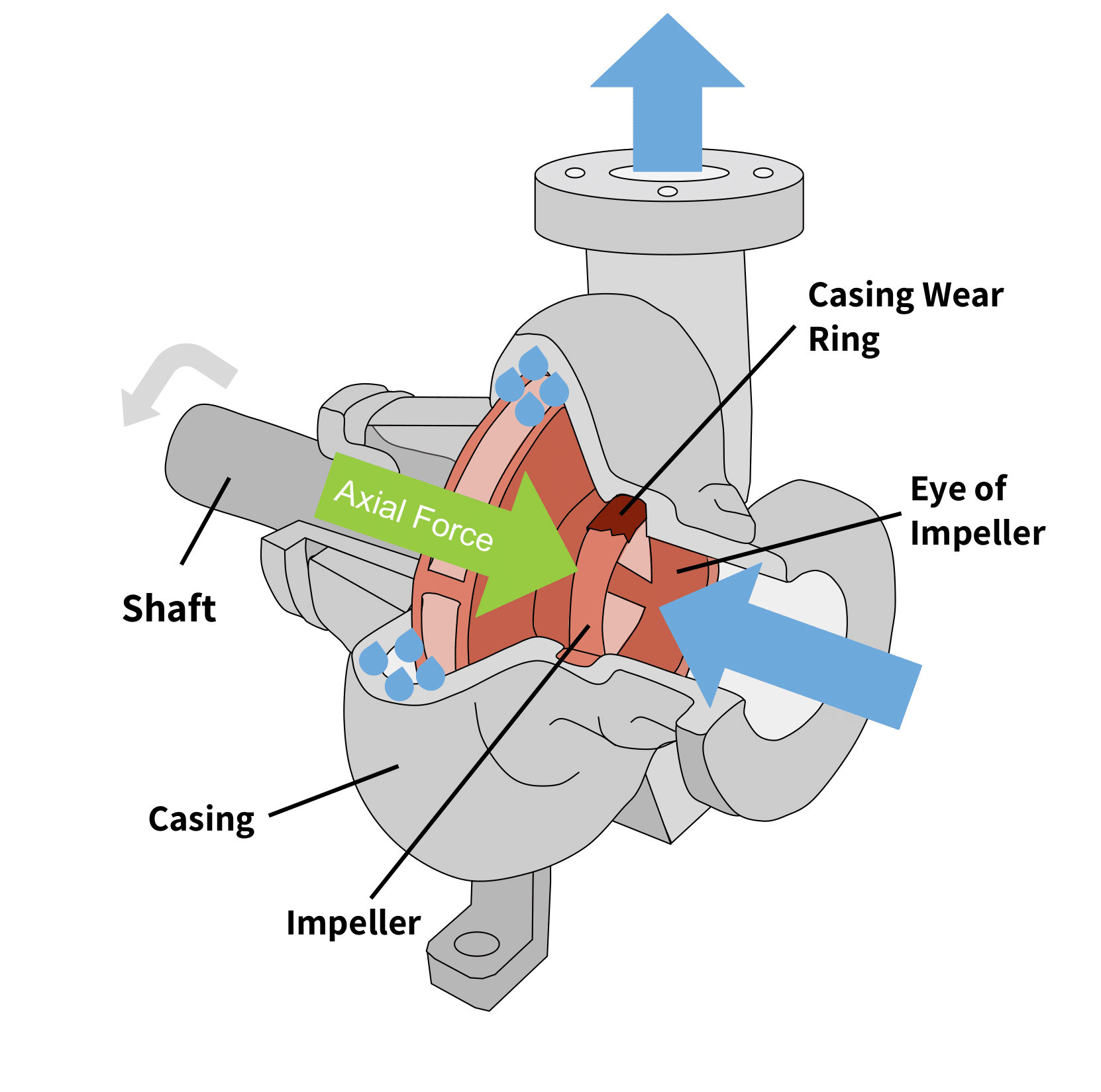
Aside from the electric motor that drives the rotation, centrifugal pumps have these components (Figure 2):
- The impeller: A rotating part of the centrifugal pump that connects to the driving unit with a shaft. It has backward-curved vanes or blades that push the fluid particles towards the outlet as the impeller rotates. There are different types of impellers: the open impeller, semi-open impeller and shrouded impeller.
- The volute casing: A specially-designed spiral casing whose cross-sectional area increases along the direction of fluid flow. This design helps to force fluid out the discharge side.
- The external casing: The external covering that protects the pump. It houses balancing holes, or points where balancing weights are affixed to ensure that the collective center of mass of the pump’s internal components aligns with the center of mass of the motor’s rotor shaft.
- The shaft: Connects the impeller to the driving unit.
- Bearings: Located on the shaft, they help maintain radial and axial thrust load clearance. A double suction impeller has bearings on both the front and back of the shaft.
In centrifugal pumps, axial thrust develops primarily through three mechanics:
- Impeller Pressure Differential: Fluid pressure acting on the back shroud of an impeller is higher than the suction pressure at the inlet eye, driving the shaft toward the suction inlet.
- Fluid Momentum Change: As fluid transitions from axial entry to radial discharge, the change in momentum exerts a reactive force along the shaft axis.
- Dynamic Unbalance & Wear: Over time, particulate buildup or vane erosion creates dynamic force imbalances that amplify axial thrust fluctuations.
Axial thrust on the rotating shaft is more substantial in multi-stage pumps. Pump manufacturers mitigate these forces using thrust bearings, balance pistons, or impeller vane arrangement. These reduce stress on shaft bearings and prevent damage to the pump’s protective seal. However, continuous axial force monitoring is necessary to verify balance performance and prevent mechanical breakdown.
The Role of Load Cells in Balancing Axial Thrust
Measuring axial forces in real time allows operators to know immediately if a pump becomes out of balance. Furthermore, measured loads can provide input to a control system that stops the rotation in an instant to prevent damage.
Several types of load cells (described in An Overview of Load Cells) exist for this purpose. However for many applications, including for measuring thrust, a strain gauge load cell is the most convenient and cost-effective. Their many spring element geometries mean many options exist for accommodating a variety of physical space configurations. Figure 3 below shows a simple strain gauge load cell.
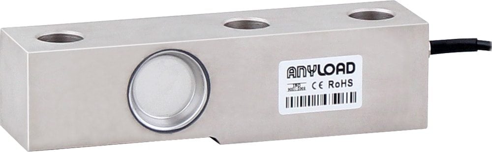
When a force is applied to the loading point of this type of load cell, the strain gauges within it deflect. This increases the overall electrical resistance across the gauges. This measured difference in resistance creates an electrical signal directly proportional to the force applied by the load. (See The Versatile Strain Gauge Load Cell for a more detailed explanation of this device’s operation.) By rigging the shaft to the cell’s load point as described in the next section, axial thrust can be measured.
7 Steps to Design an Axial Thrust Measurement System
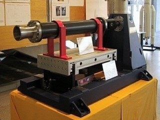
To monitor axial thrust using a test stand as shown in Figure 4, follow these steps.
1. Calculate Maximum Expected Thrust
Calculate peak thrust forces using fluid density, operating pressure, and rotor dimensions. Select a load cell with a full-scale capacity exceeding this calculated maximum to handle dynamic pressure spikes.
2) Select a Bi-Directional Load Cell
Because thrust forces can reverse direction during pump startup, transient flow, or shutdown, select a universal/bidirectional load cell (capable of measuring both tension and compression).
3) Factor Environmental and Performance Specs into the Choice of Load Cell
Evaluate environmental factors such as temperature, fluid exposure, and IP rating. Review datasheet specs for non-linearity, hysteresis, and overload ratings (see How to Read a Load Cell Datasheet), as well as safety certifications required for the environment. Select the load cell that meets these and the criteria determined in steps 1 and 2.
4) Construct a Rigid Thrust Stand/Frame
Build a rigid frame that positions the cell’s load point directly along, and orthogonal to, the shaft center line. Incorporate mounting hardware such as self-aligning spherical washers or button mounts to ensure forces remain purely axial and eliminate off-axis side loading. Self-alignment systems are critical since centrifugal pumps intermittently become unbalanced during use.
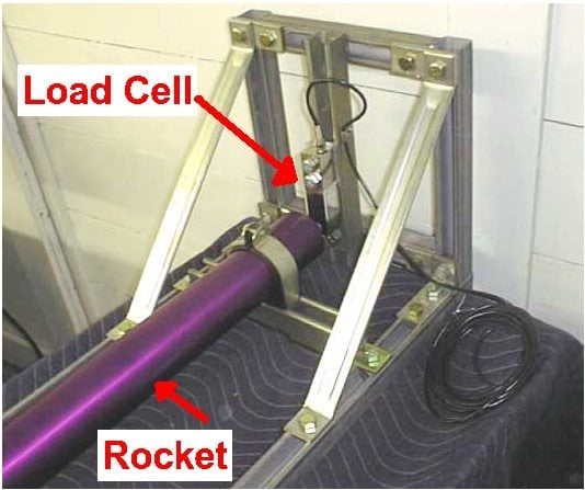
5) Condition the Output Signal
Pass low-voltage mV/V outputs through an instrumentation amplifier and active low-pass filter to strip out rotational mechanical noise and high-frequency motor vibration prior to ADC conversion and measurement display.
6) Calibrate the System Assembly
Perform multi-point calibration using a hydraulic ram or calibrated reference weights applied along the thrust axis to verify linearity, hysteresis, and zero-load tare offset. This will be necessary not only before assembly deployment, but periodically to adjust for drift with use.
7) Mount, Test, and Commission
Mount the pump to the measuring system. Verify all electrical shields and grounds, and execute initial low-speed trials before running full-power flow testing. Perform tests in a controlled environment under proper supervision and approval.
Summary: Implementing Thrust Measurement
Designing a dedicated axial thrust measurement system validates pump performance curves and protects rotating equipment by alerting technicians to pre-failure mechanical wear. Browse Tacuna Systems’ catalog of strain gauge load cells and signal conditioners, or contact our engineering team for assistance designing custom thrust measurement systems.
References
- An Overview of Load Cells
- The Versatile Strain Gauge Load Cell
- How to Read a Load Cell Datasheet
- Why Do I Need a Load Cell Amplifier (and Other Signal Conditioners)?
- Calibrating the Force Measurement System
- Centrifugal Pumps by Dan Campbell, Noah Brown, John Cox
- Centrifugal Pumps by Christian Allerstorfer