
In the article, The Versatile Strain Gauge Load Cell, we explain the internal bridge circuitry of this measuring device. Knowledge of this internal Wheatstone bridge circuit naturally leads to the conclusion that it is a four-wire system. These four wires connect the load cell to required input voltages and output signal conditioners that are also part of the measuring system.
However other wiring configurations exist. Some load cells add two sense wires to compensate for changes in resistance if the load cell’s cable length is changed. This creates the six-wire load cell. The remainder of this article explains the difference between a four-wire vs. six-wire strain gauge load cell at the bridge level.
Key Takeaways
- The article discusses load cell cabling, differentiating between four-wire and six-wire configurations.
- The four-wire load cell uses two wires for power and two for signal output, while the six-wire configuration adds sense wires for voltage compensation.
- A six-wire load cell allows the attached amplifier to sense and compensate for resistance changes in the input wires due to temperature or changes in the length of wire. This makes six-wire load cells more tolerant of environmental factors and alterations to the measurement system installation.
- The shield wire present in both configurations protects against electromagnetic interference.
- Tacuna Systems offers both types of load cells to meet our customers’ needs.
The Four-Wire Load Cell
In the four-wire system, two wires supply power to the Wheatstone bridge: the positive and negative input terminals. The other two wires are the signal output terminals of the bridge, likewise positive and negative. Figure 1 shows this wiring system, typically found in a bending beam load cell.
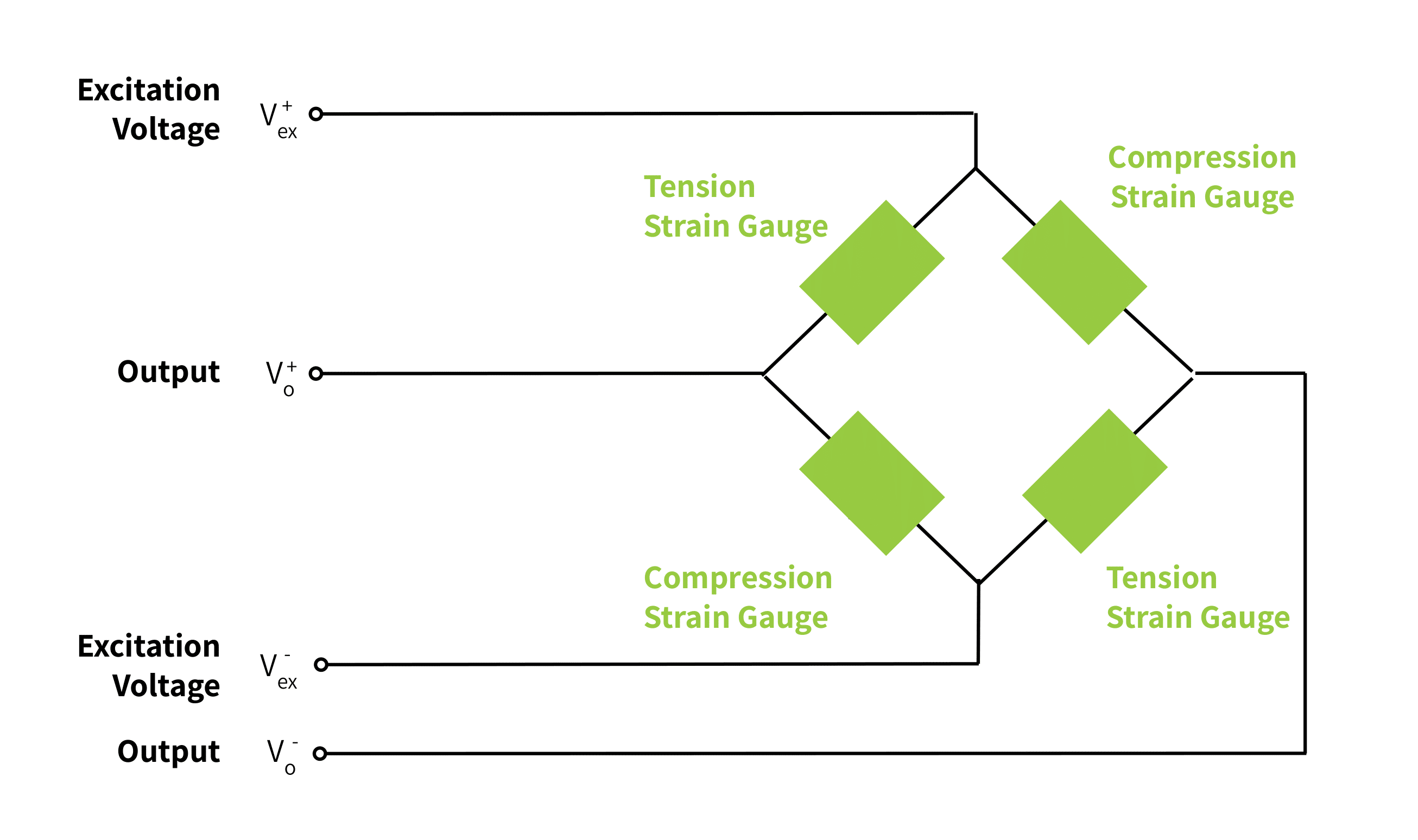
Most textbooks and articles show the lumped parameter model of the strain gauge Wheatstone bridge and its connections. The lumped parameter model ideally assumes that the connecting wires to and from the Wheatstone bridge have zero resistance.
However in practice, there is a detectable voltage drop over the wires themselves. This is not a problem as long as the length of wire at both the inputs and outputs remains unchanged throughout the usable life of the load cell. All of the load cells in Tacuna Systems’s online catalog are precalibrated with this known length of wire; therefore their wire resistance is accounted for in the performance characteristics listed on their specification sheets.
As a few of our FAQ questions point out, cutting cables alters the calibration of a four-wire load cell; however inserting a cable connector in a same-length cable run will not measurably alter a load cell’s calibration. The connector may be practical to more easily exchange out a load cell from a measuring system.
In applications where it may not be practical to keep extra lengths of wire, or applications requiring longer cables, a six-wire load cell may be more desirable.
The Six-Wire Load Cell
In practice, a distributed parameter model is more accurate than the lumped parameter model of the bridge circuit. This model assumes connecting wires actually have resistance to the flow of current. This means the wires’ length, cross-sectional area, and resistance variation with temperature influence the bridge’s design.
A six-wire strain gauge load cell accounts for the effects of these distributed parameters. It has the same power supply/excitation and signal output terminal wires as its four-wire counterpart. However it also has a positive and negative sense wire. The sense terminal wires connect at one end to the same nodes as the power supply wires. Figure 2 below illustrates this.
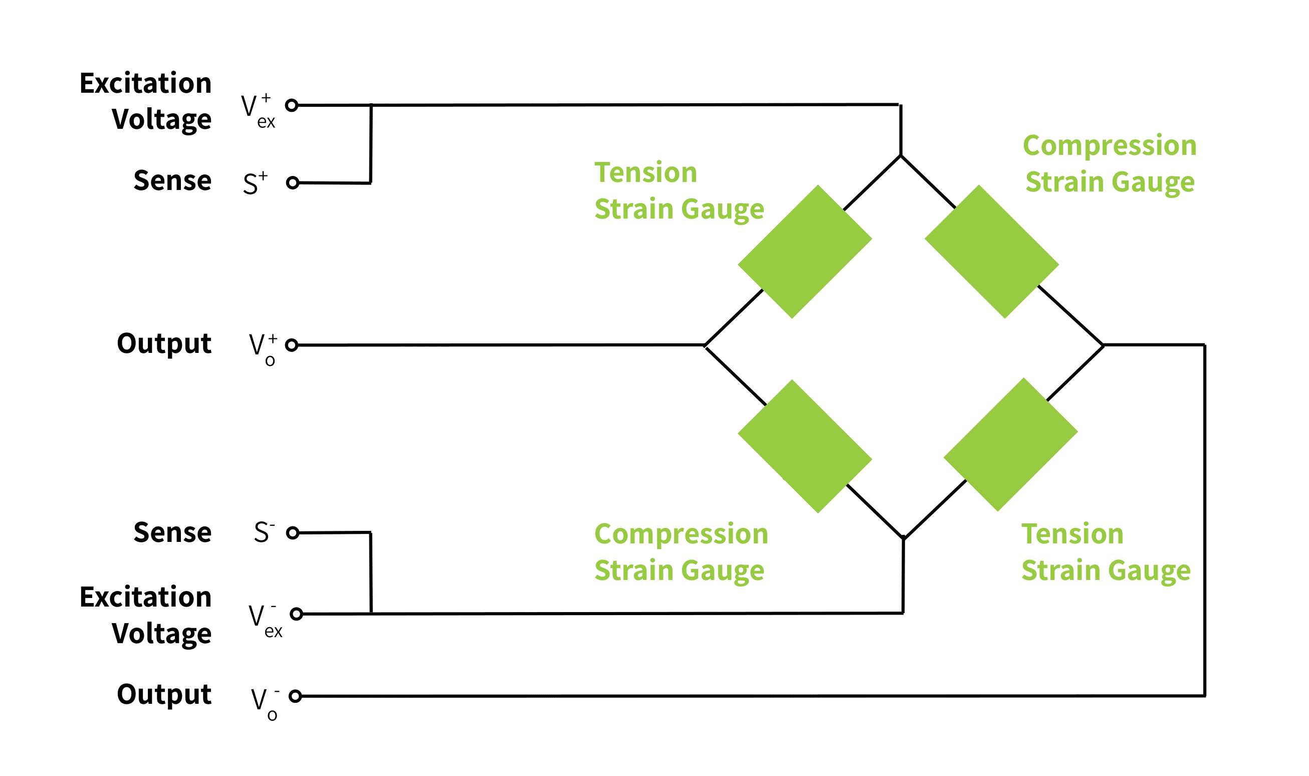
The other end of these sense terminals connects to the input port of an amplifier; the output of the amplifier then connects to the power supply terminals of the load cell, forming a loop.
In this way, the amplifier detects the actual voltage powering the load cell. The amplifier can then make necessary adjustments to keep the voltage supply at the desired operating level. This compensates for any voltage drop across the cables, which can vary with temperature during use. This also makes the system insensitive to any changes made to cabling. To summarize, the six-wire system integrates a simple voltage controller design with the Wheatstone bridge.
Other Strain Gauge Load Cell Wiring
An additional wire may be present in both the four- and six-wire strain gauge load cells. This wire is called the shield wire. The shield wire does not connect to the strain gauge circuitry; rather it connects to the body (structural element) of the transducer. It protects this internal circuitry from electromagnetic interference.
A Practical Example of the Six-Wire Connection
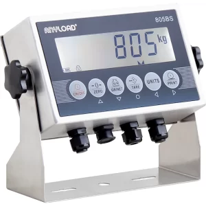
Most of the load cells in Tacuna Systems’ online catalog are available for special order with a six-wire configuration. The 805BS Load Cell Indicator is capable of either 4-wire or 6-wire configuration.
Conclusion
This article compares the four- and six-wire electrical connections of strain gauge load cells, and explains the additional shield wire. Note that the same sense wire compensating technique can be applied to other transducer types.
Design and implementation considerations beyond the scope of this article exist. These are discussed in more detail in the articles below.
Further Reading
- Load Cell FAQ
- Choosing the Right Load Cell For Your Job
- Why Do I Need a Load Cell Amplifier?
- Load Cell Summing: Junction Boxes, Signal Trim, and Excitation Trim
- Calibrating the Force Measuring System
- …and other articles in the “Load Cell How To” section of our Knowledge Base.
References
- The Instrumentation Reference Book Edited by Walt Boyes
- Force Measurement Glossary by Tacuna Systems