

Building a digital scale is an excellent project for practicing the fundamentals of embedded electronics. Ideal for hobbyist prototyping or school science projects, this guide provides step-by-step instructions for anyone with a basic grasp of hardware wiring and introductory coding.
The components used to build the digital scale in this article can be found in the Tacuna Systems shop.
Key Takeaways
- Embedded System Fundamentals: Learn to construct a functional digital scale using basic hardware wiring and open-source programming skills.
- The Core Hardware Stack: The system integrates four essential components: a strain gauge load cell (5kg), a 24-bit signal conditioner (HX711 ADC), an Arduino Uno microcontroller, and a data display.
- Essential Calibration: Uploading dedicated calibration firmware establishes the exact scaling factors required to convert raw analog data into accurate weight units. This is the essential final step to create a reliable, working scale.
Practical Field Application: For a look at a similar architecture in a field deployment, read our case study, Winging It: How a Tiny Scale Is Unlocking A Petrel’s Feeding Secrets.
What is a Digital Weighing Scale?
Digital weighing scales are common in our everyday lives, from the produce section grocery stores to our own bathrooms.
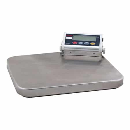
A digital scale is an electronically operated device that displays the weight/size of an object placed on it in numbers and units. This display is usually liquid crystal or 7-segment display.
Core Scale Hardware Components and Electrical Functions
Now that we have established what a digital scale is, this section lists and describes its fundamental internal components.
The Strain Gauge Load Cell Transducer
A load cell functions as both a sensor and a transducer. As a sensor, the device detects mechanical force (weight) and undergoes a physical change, such as structural deflection. As a transducer, it converts that physical deflection into a proportional electrical voltage signal. While all transducers inherently rely on a sensing element, a component is explicitly a transducer because it translates that raw physical change into a readable electrical output.
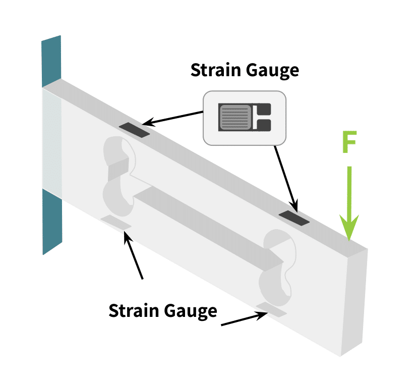
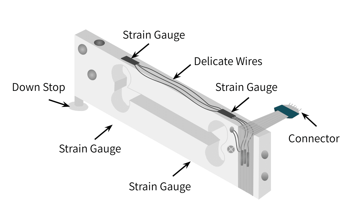
Examples of load cells are the pneumatic load cell, hydraulic load cell, strain gauge load cell, or capacitive load cell (See An Overview of Load Cells for more information). The most common type used in digital scales is the strain gauge load cell. This load cell is a transducer that uses a strain gauge as its underlying mechanism. The strain gauge has a resistive and elastic metal foil material that is fixed and attached to the bending parts of the load cell as shown in the figures below.
The Signal Conditioner (Amplifier & ADC Chip)
The signal conditioner is a specialized circuit device that performs two foundational operations: it amplifies the load cell’s raw differential voltage output and filters both its input and output paths.
A load cell’s full-scale output signal is exceptionally small, typically measured in millivolts (\(mV\)). Furthermore, incremental weight changes during operation produce minute signal differences on the order of microvolts (\(\mu V\)). Because microcontrollers cannot natively resolve such low-level analog fluctuations, a signal conditioner is critical to amplify the transducer’s output to a usable level.
Load cell signal processing demands a highly precise, low-noise component known as an instrumentation amplifier. In modern hobbyist and industrial setups alike, filter circuits, amplifiers, and a high-resolution 24-bit analog-to-digital converter (ADC), such as the HX711 chip, frequently appear together on a single breakout board or integrated circuit.
Engineer’s Note: Why 24-bit Resolution Matters:
A standard Arduino Uno features a built-in 10-bit analog-to-digital converter (ADC). This means it divides its 5V reference voltage into \(2^{10}\) or 1,024 discrete digital steps, resulting in a minimum detectable voltage step of roughly 4.88mV.Because a 5kg load cell only outputs tiny microvolt changes (\(\mu\text{V}\)) when small weights are added, the Arduino’s native ADC is completely blind to them. Even if you amplified the signal by a factor of 128, a \(10\ \mu\text{V}\) change only becomes \(1.28\text{ mV}\). This is far too small to trigger even a single step on the Arduino’s 10-bit converter. The scale would read zero change.
By using a dedicated 24-bit ADC like the HX711, the voltage range is divided into \(2^{24}\) or 16,777,216 discrete steps. At a gain of 128, the HX711 has a full-scale differential input range of \(\pm 20\text{ mV}\). We can calculate its mathematical resolution limit using the following formula:
$$\text{ADC Step Size} = \frac{40\text{ mV}}{2^{24}} \approx 2.38\text{ nV}$$
With a resolution of roughly 2.38 nanovolts per digital count, the system can easily capture microvolt-level signal shifts, translating tiny physical weight adjustments into precise numerical data.
This hardware configuration filters out environmental noise and electromagnetic interference (EMI) that could otherwise compromise the integrity of the amplified force data. Additionally, it cleanly decouples stray AC noise signals from the stable DC output line. Tacuna Systems offers a high-fidelity signal conditioning device described at this link.
The Microcontroller Unit (MCU Processing Hub)
This is the central processing unit of the whole digital scale. The analog output of the signal conditioner flows to the analog input port of the microcontroller, which in turn converts this analog signal to digital. Note that some signal conditioners have an analog to digital converter circuit together with the amplifier circuit and the filter circuits on a single chip. This reduces the workload on the microcontroller, as the output of the signal conditioner instead goes to the digital input port of the microcontroller. The microcontroller then reads the clocked digital pulses from the conditioner to obtain the data it processes to determine the weight displayed. Finally, the microcontroller computes the weight and then displays it through its connected LCD screen.
The Liquid Crystal Display and Serial Monitor Interfaces
As explained above, this is the screen that connects to the microcontroller to display the weight.
Step-by-Step Circuit Integration and System Coupling
To build a digital scale yourself, we will use the following components coupled together:
- A 5kg load cell
- An HX711 amplifier
- An Arduino Uno Microcontroller Unit (MCU)
- Any suitable output screen (in this case an Arduino IDE Serial Monitor)
Project Technical Profile
- Application Category: DIY Electronics, Embedded Systems, & Force Measurement Prototyping
- Core Components: 5kg 4-wire Single Point Strain Gauge Load Cell, HX711 24-bit ADC breakout board, Arduino Uno MCU platform.
- The Integration Challenge: Converting analog, low-voltage differential microvolt signals into clocked digital pulses readable by an open-source microcontroller, followed by calculating the precise calibration scaling factors (
FINAL_Scale_FactorandFINAL_Offset_Value).
The next two sections explain the process for connecting these components.
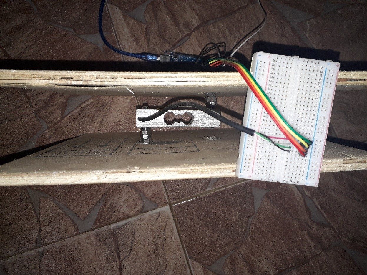
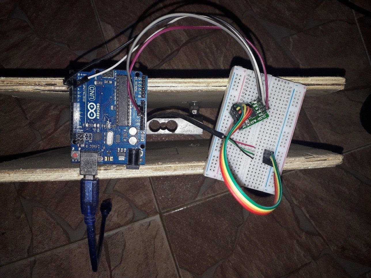
Note that in Figure 4, the scale is turned on its side to show the connections. Notice there are two wooden boards connected to alternate ends of a single point load cell. One board forms the base and the other the loading platform. Any convenient flat, sturdy material can form these two components.
Pinout Topography and the Hardware Setup
The 5kg load cell for this project has four wires (some load cells have 6). The wires are as follows, according to the load cell’s datasheet.
- Red wire is the positive power supply
- White wire is the Ground of the power supply
- Black wire is the positive output
- Green wire is the negative output
Any extra wire, which might be any color such as blue or yellow, is the ground wire for EMI. It should be connected to the power supply ground.
Engineering Caution: Verify Your Specific Wire Colors
Load cell wire color coding is not universally standardized across the electronics industry. While the project in this article uses a specific configuration from our manufacturer’s datasheet, another common standard flips the white and black wire assignments entirely.
Connecting your excitation voltage (E+ or E-) to the sensitive signal inputs of your amplifier (A+ or A-) can cross lines inside the sensor, permanently destroying the delicate internal Wheatstone bridge strain gauge network or short-circuiting your HX711 chip.
Never blindly follow color charts from generic internet diagrams. Before powering up your circuit hub, always cross-reference your wiring connections directly with the exact engineering datasheet supplied with your specific load cell unit. If you are using a 6-wire load cell instead of a 4-wire cell, remember to tie the positive sense to positive excitation (Sen+ to Ex+) and negative sense to negative excitation (Sen- to Ex-).
Wiring Configuration: Load Cell to HX711 Breakout
The wires listed above attach to the appropriate pins of the HX711 amplifier device as shown in the sets of pictures below. The HX711 is a special amplifier that has 2 channel inputs A and B, each with different amplifier gains adjustable by a computer program. The channel A has a gain of 128 and 64, while the channel B has a fixed gain of 32.
Note this HX711 device matches the description of the type of signal conditioning device that has an amplifier, filter, and analog-to-digital converter (ADC) embedded together on a single chip. This means its data output goes to the digital input pin of our microcontroller instead of its analog pin.
Therefore, connecting the HX711 and the load cell is as followed:
- Red wire/Positive supply -> E+
- White/Negative Supply -> E-
- Green/Negative Ouput -> A-
- Black/Positive Output -> A+
Pin Mapping: HX711 to Arduino Uno MCU
After connecting the amplifier, the next step to build the digital scale is to connect the microcontroller. The HX711 connects to the Arduino MCU as follows:
- VCC -> 5V supply on Ardunio
- GND ->GND
- CLK -> D2
- DOUT -> D3
Firmware Execution: Writing the Arduino Sketches
Once the hardware connections are complete, the next step to build the digital scale is to upload the program code to the MCU from a PC through the Arduino IDE. The process and the code have two subdivisions: the calibration code and the weighing code.
Firmware Phase A: Execution of Calibration Sketches
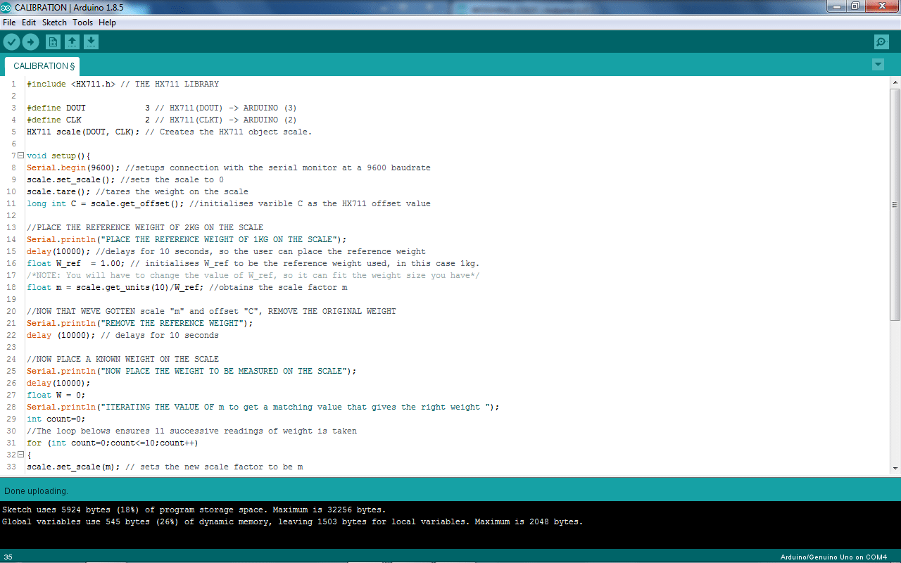
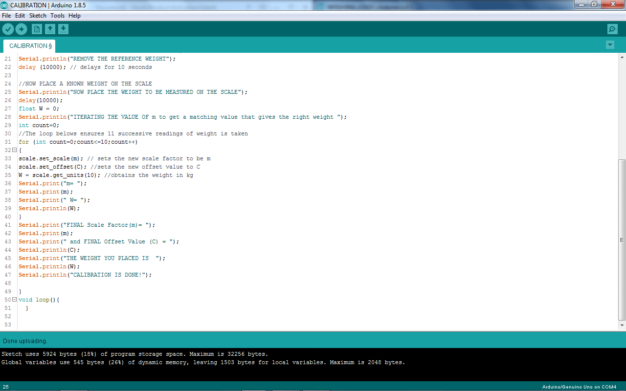
The calibration code is the program used to calibrate the load cell transducer. Calibration configures the load cell output to always give a precise value of weight and at the particular SI unit such as Kilograms, Grams, Tons, Pounds etc.
The HX711 library code contains a good guide on how to calibrate the load cell. The calibration code is shown in Figure 6a-b.
The results of the calibration process are shown below in the Serial Monitor of the Arduino IDE.
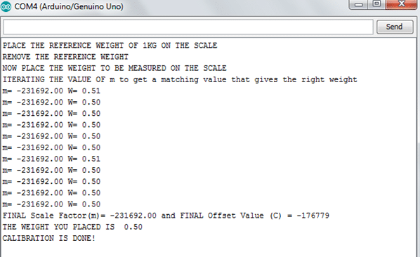
Note in Figure 7 the “FINAL Scale Factor” and the “FINAL Offset Value”. These values are critical to obtain before uploading the weighing code.
Firmware Phase B: Launching the Active Weighing Script
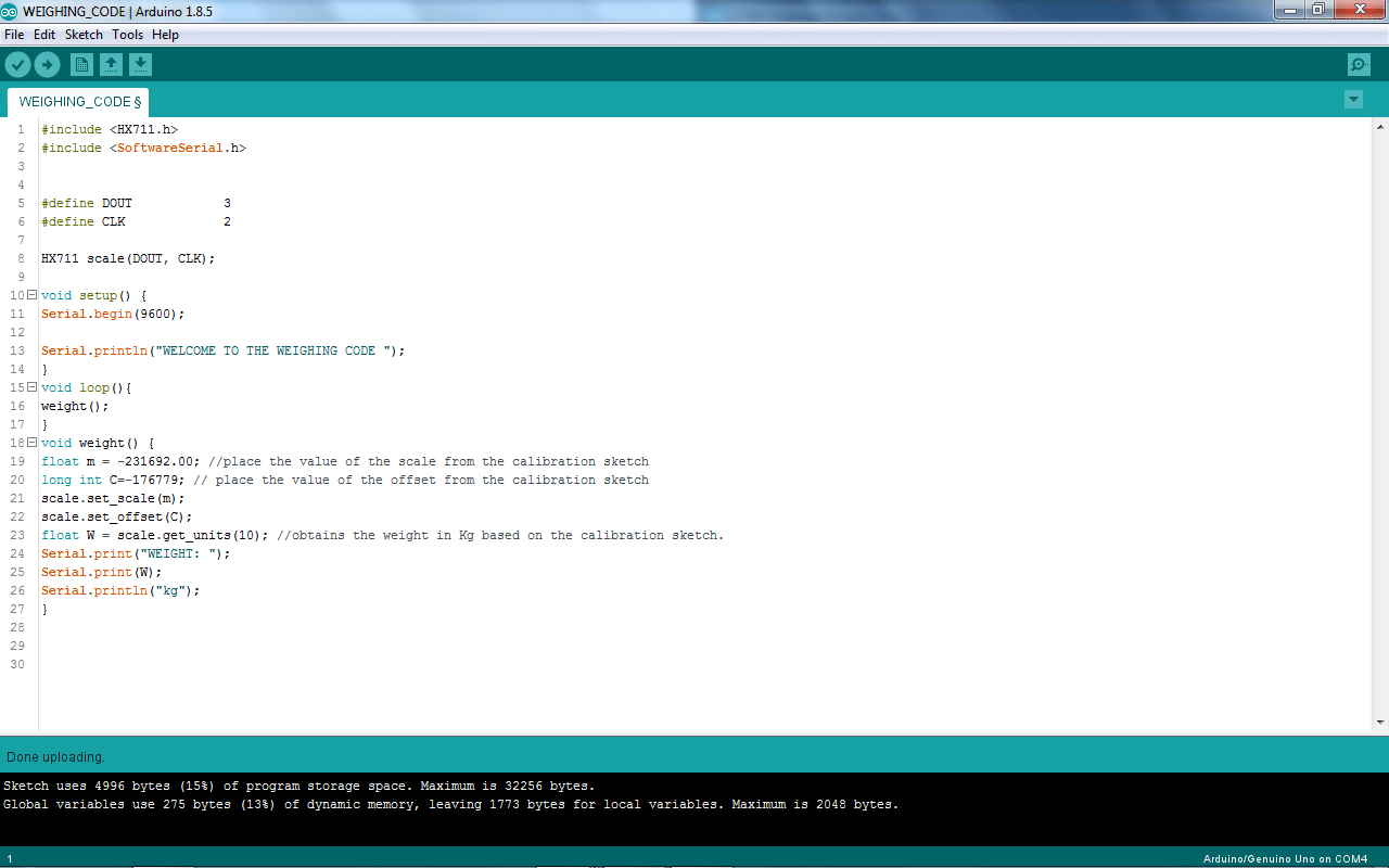
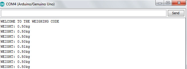
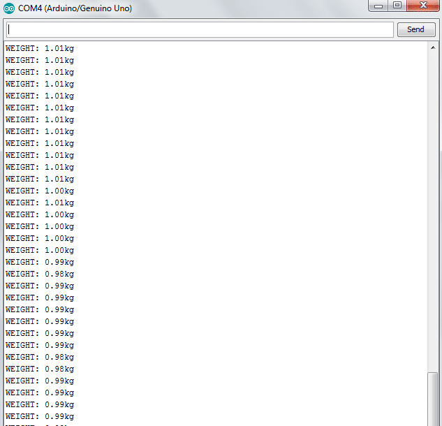
Once calibration is complete, the weighing code uploads to the MCU. This code appears in Figure 8 below. The figures that immediately follow, Figures 9a-b, show the readouts for a 500g weight (top) and a 1kg weight (bottom).
And with that, the process of building the digital scale is complete!
Conclusion
This article has presented one way to build a digital scale. It also provides some insight into how these scales work. The components are easily obtained from our shop. For a fun, real-world example of a similar scale, dressed up a bit to enable groundbreaking sea bird research, see Winging It: How a Tiny Scale Is Unlocking A Petrel’s Feeding Secrets.
If you are not inclined to build your own, Tacuna Systems offers a full range of scales, listed below.