
You would not buy a sports car if you planned on towing a trailer, the same way you wouldn’t rent an excavator to dig a fence post-hole. The key to starting any job is having the right tools and equipment. This is especially true for load cell and force measurement applications. The right load cell is critical to obtaining high-quality, accurate readings. But how do you choose the right one?
Fortunately, industrial load cells come in a wide variety of designs and sizes to fit myriad tasks, orientations, load magnitudes, and environments. The key is to find the right match, taking into account all of these criteria simultaneously. This article first reviews the science behind the features of each load cell design category and then provides high-level recommendations for choosing a load cell based on its strengths. (See this table at the end of this article for a quick summary.) For specific project recommendations, Tacuna Systems offers complementary design guidance (like that which we gave to the researchers in this interesting featured customer project).
Note, this article focuses specifically on strain gauge load cells. Check out An Overview of Load Cells for a summary of the different types.
Key Takeaways
- Choosing the right load cell is crucial for accurate, cost-effective force measurement.
- Define your application’s requirements for these factors:
- Load orientation and how many vectors need to be quantified, taking into account the types of load cell stresses such as normal, bending, shear, and torsion;
- The physical space where the load cell must fit;
- The maximum forces the load cell will undergo, including shock loading and environmental loads (wind, vibration);
- Any corrosive, abrasive, moisture, or thermal exposure that could damage a delicate load cell;
- Short- vs. long-term budgetary constraints, considering the tradeoff of quality vs. long-term maintenance or replacement.
- Select the right load cell type based on application requirements.
- See the summary of load cell types and their best applications at the end of this article.
1) Consider the Load’s Orientation
A load cell is a sensor device that converts the energy of an applied force into a quantifiable electrical signal. The strength of the signal is proportional to that force — compression, tension, pressure, etc. Therefore, an accurate reading requires the vector components of the force to align completely with the force direction that the load cell design expects. Whereas this perfect alignment is impossible in real-world environments where vibration, force shunts, and other environmental effects are the norm, the right load cell shape and mounting hardware can account for these situations.
Load cell design is also influenced by the mechanical principle of stress. Stress describes the intensity of the internal forces acting on a specific section of an object under load. For example, if you bolt a steel I-beam to a wall and hang a 500 lb. weight from its free end, the beam’s cross section toward the middle of the span will experience different stress levels than at its fixed end, free end, or any cross section in between. A load cell body’s shape exploits this principle to improve accuracy.
Because the understanding of how stress and load orientation influence a load cell matters when choosing the right one, this section reviews both concepts. We will cover
Normal Stress and Normal Loading
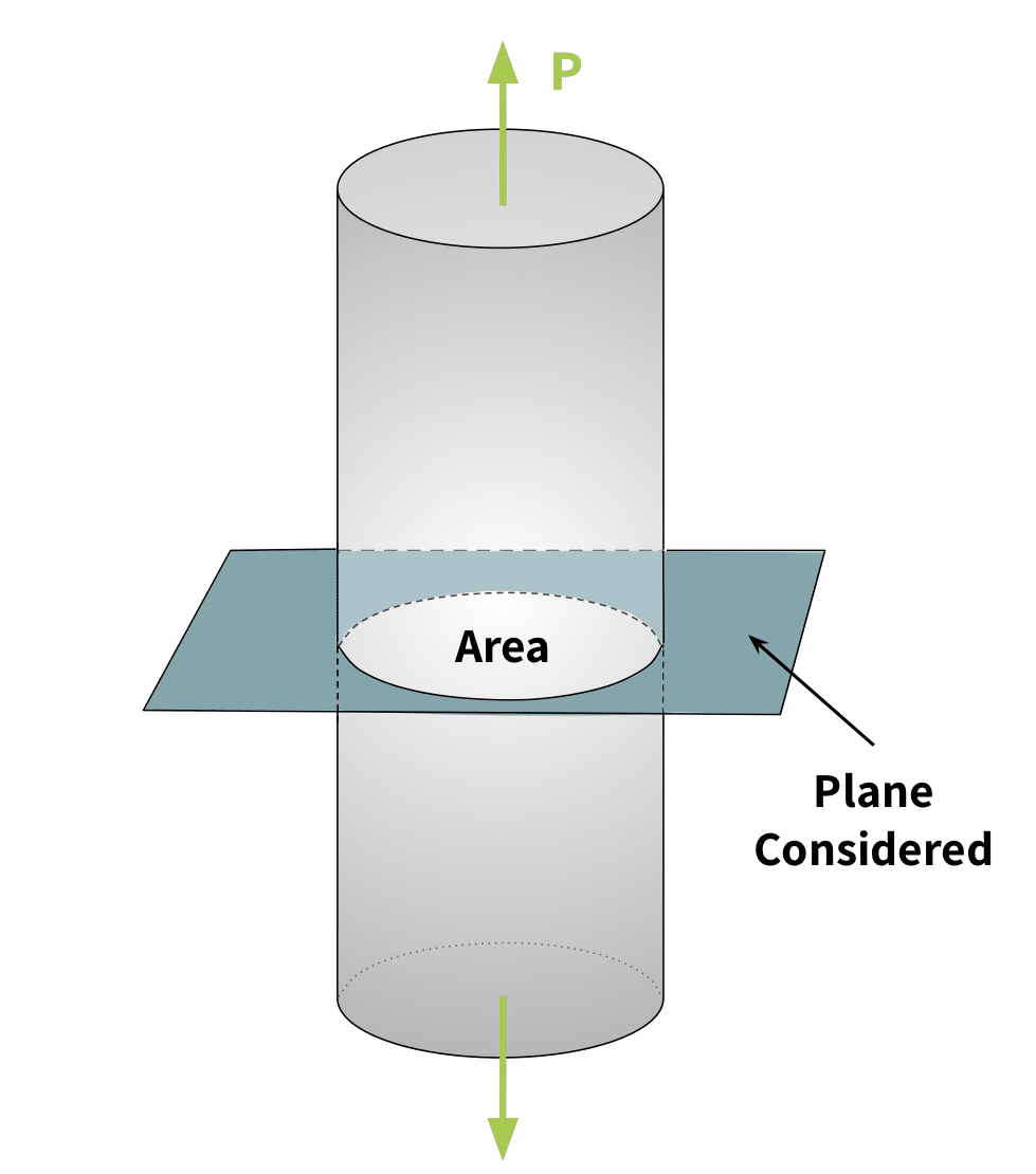
A normal load is a force whose direction is exactly perpendicular to a defined plane or surface it acts upon. Normal stress is stress due to that force. This is the simplest type of stress (“\(\sigma\)” in equations) to calculate since it is based only on the force applied (\(P\)) and the cross-sectional area (\(A\)) affected by the force. That is,
\( \sigma = \frac{P}{A} \)
Normal stress can be either tensile or compressive. Tensile forces pull or stretch the body, while compressive forces squeeze the body.
Grocery or postage scales are examples of measurement systems that leverage normal loads. For these scales, the load direction is exactly perpendicular to the scale plate, which, in turn, rests on the load cell load point.
Note that normal stress differs from normal loading. Load cells designed for normal loading do not always experience normal stresses. They can undergo shear stress and bending as described below.
Bending’s Effect on Stress
Bending is when an external force or moment applied to a structural element causes it to bend. An object’s reaction to this external force differs from its reaction to a normal load. Half of the element sees tensile normal stress, while half of it sees compressive normal stresses. See Figure 3.
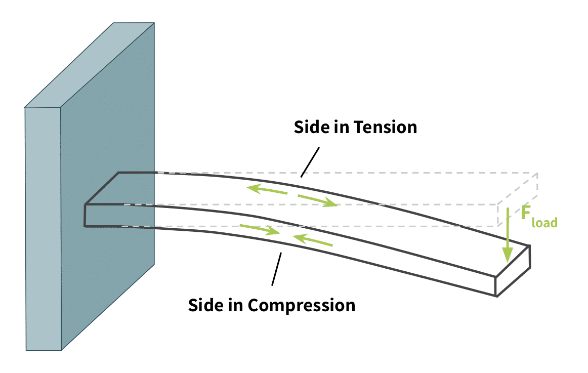
Some load cell designs exploit this stress differential on a bending beam to compensate for environmental factors.
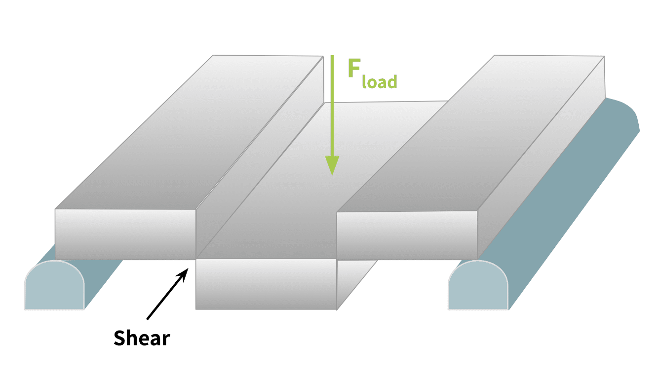
Shear Stress
Shear stress is a stress component that acts in the considered plane, much like a sheet of paper between two opposing blades of scissors. The point of maximum shear is where the opposing blades meet and cause the paper to shear into two parts. Figure 4 below labels the shear force created by the normal load \(F_{load}\) and models the deformation in the structure created by it.
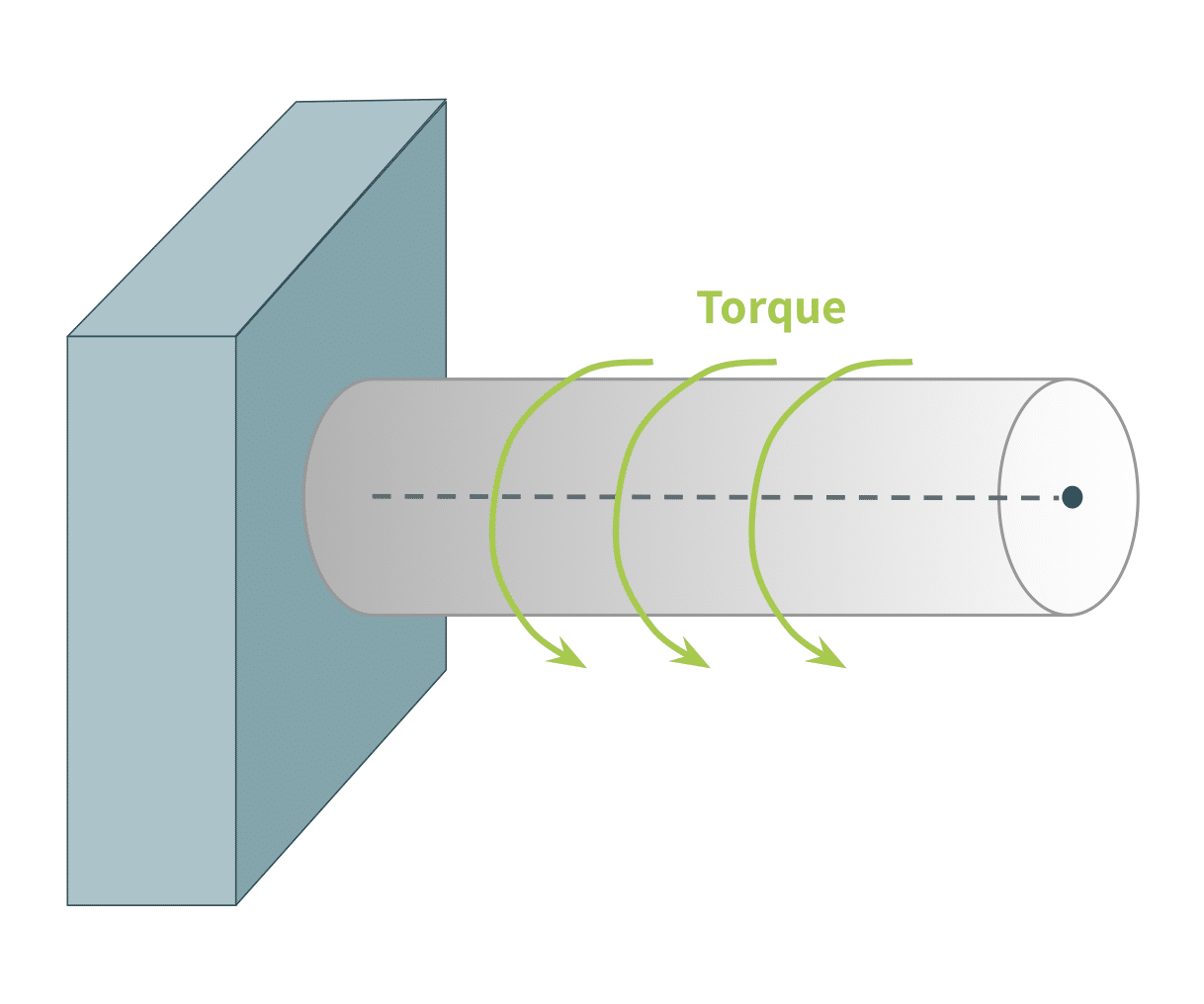
Torsion
Torsion is a type of stress that occurs when an applied external force (or “torque”) causes the structural body to twist. All rotating or spinning objects experience it, including wheel axles, driveshafts, gears, motors, propellers, etc.. The figure below illustrates this force on a beam fixed at only one end. In this figure, where the beam’s cross-section is uniform from end to end, torsional stress will vary only radially, with maximum stress on the beam’s outer surface, and zero along its center axis.
2) Consider the Object to be Weighed: Capacity, Resolution, Shape
Another factor to consider when choosing a load cell is its load cell class. Each load cell is categorized into a “class” according to its resolution and rated capacity.
Rated Capacity: This specification determines the heaviest object the system can bear without losing accuracy. When choosing a load cell’s maximum capacity, consider any environmental factors that could add axial weight components. (See “Vibration and Wind” below.)
Resolution: This load cell attribute is given in “divisions” or fractions of the measuring range that the load cell can sense. It influences the smallest weight difference detectable by a measuring system. (For more details on this point, see the article, What Is the Lowest Weight a Load Cell Can Measure?)
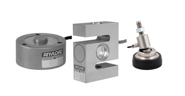
Likewise, a load cell body’s shape is an important consideration for your choice of load cell. Some are beams, some are S-shaped, and still others may be canister-shaped.
Shape: This attribute is meant to fit the geometry of the mounting structure (such as a hopper) while aligning correctly with the load direction and properly capturing the type of applied forces (as Section 1 describes). The variety of load cell shapes accommodates a wide range of uses.
Always choose a load cell whose shape, mounting, and capacities conform to the physical space, maximum and minimum weights, and smallest weight variances of the measured object.
3) Consider the Environment the Load Cell Will Operate In
Many environmental factors affect the operation of a load cell, and therefore should influence the choice. Specifically, these factors determine the best material for the load cell body, its IP rating, and (as alluded to before) its rated capacity.
Moisture
One of the most damaging environmental conditions for a load cell is moisture intrusion. It can cause corrosion of the load cell material, short circuits in its electronics, and other failures. However, load cells often operate in environments where moisture is a given, whether they be outdoors or in areas such as food preparation environments, where equipment must be cleaned to maintain sanitary standards.
Chemical Exposure
Like moisture intrusion, chemical exposure can cause corrosion in the load cell material and similar failures. This factor requires special consideration in environments such as food preparation or medical environments, where equipment must be cleaned to maintain sanitary standards, or any industrial application where chemical exposure is expected.
Temperature
Temperature can make a tremendous difference in the operation of a strain gauge load cell, since the load cell uses electrically resistive elements. Temperature-related expansion and contraction can significantly affect this resistance. A system designer must ensure that the chosen load cell can function accurately within the temperature extremes to which it will be exposed. Likewise, the load cell itself and other system components must compensate for any signal variations due to temperature.
Vibration and Wind
Vibrations, such as from seismic activity, heavy traffic, or industrial activity, can artificially add loads to a load cell. Likewise, lateral forces due to wind can add force vectors that are axial to its intended load direction. Proper installation can mitigate much of the effect of these conditions. However, the choice of load cell capacity should be high enough to withstand the maximum intended load, plus any environmental loads due to the highest winds or vibrations in the area.
4) Consider the Desired Accuracy, Error Ratings, and Ease of Calibration
Last but not least, once a measuring system’s designer considers a load cell’s mechanical form, material, IP rating, and accuracy class, they must ensure its error specifications are compatible with the system requirements as a whole. These include combined error, hysteresis, creep, non-linearity, and repeatability, as defined on the load cell data sheet.
All load cells drift with repeated use and require routine calibration to maintain performance within these specifications. Therefore, system designs should account for ease of field calibration and load cell replaceability. Load cell quality also matters: tighter manufacturing tolerances and superior materials improve long-term stability and reliable recalibration over the product’s lifetime. These can lower the cost of ownership even though the initial price is higher.
Choosing a load cell with appropriate accuracy ratings, quality construction, and reliable vendor support simplifies long-term maintenance, generates more reliable data, and reduces avoidable downtime. These factors could greatly offset the higher initial investment compared to a load cell of cheaper fabrication. The article, How Can I Tell If a Load Cell Is a Quality One? addresses these important issues.
5) Select the Load Cell Type for the Application
Now that we’ve reviewed the main forces that create stress on an object (normal, bending and shear, and torque) and the other factors that influence the best choice of load cell, we can match common types to their optimal application.
Load Cells for Normal Loading
Any scale that weighs an object on top of a platform will bear a normal load. The weight of the object is a force that acts vertically downward, causing the load cell to react. The load cell will respond with an output signal proportional to the weight of the object applied. This section describes a few load cell types in the Tacuna Systems offering.
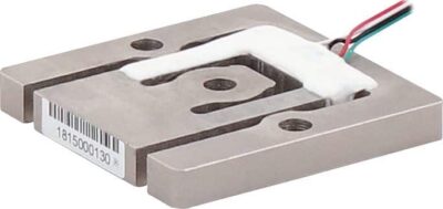
Single Point or Platform
Single point load cells are most commonly used in low capacity, compact weighing, such as balances, food scales, pricing scales, packaging scales, medical and pharmaceutical scales, on-board weighing, and other retail applications.
These load cells accommodate off-center loads by design. This makes them well-suited for simple weighing systems that use a single load cell. By contrast, larger or more complex systems often use a load cell at each corner of the weighing platform and a junction box to sum the signals. This could introduce the need for load cell trimming, a tuning process that ensures that measurements from such a multi-load cell scale remain consistent regardless of the load’s placement on the platform.)
The Tacuna Systems product line of single point load cells ranges in capacities from 300g to 2000kg.
For a look at innovative uses for these types of load cells, see these articles in our “Featured Customer Projects” section of our Knowledge Base: Load Cell Research Example: Hydrodynamic Characteristics of Freshwater Snails, Measuring Contact Forces on Soft Materials for Medical Robotics and Other Applications, and Bearing the Load of Social Responsibility.
Canister and Disk Load Cells
Canister or disk load cells are a type of load cell used specifically for compression loads. The load passes through the top of the “button” of the device. Strain gauges at the internal core of the load cell measure compressive normal loads.
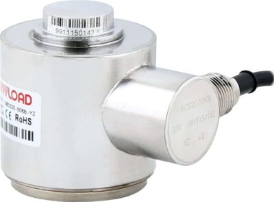
Canister load cells are designed to handle much heavier loads, but are much bulkier than other compression load cells. The sturdy design is resistant to bending loads and side loads, making these devices ideal for systems with several directional load components where only one must be quantified. Tacuna Systems offers products with capacity ratings ranging from 25 to 500,000 kg.
Miniature Load Buttons
Miniature load button load cells are a type of small canister load cell for lighter capacities, between 5 to 45 lbs.
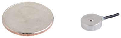
They commonly appear in small retail and postal scales. As with other canister load cells, miniature load button load cells are designed for applications involving multi-directional forces while isolating and measuring only the force component of interest. You can read about interesting research examples that used these types of load cells in Load Cells in Education: Neuromuscular Aspects of Human Movement Force Measurement, and Measuring Contact Forces on Soft Materials for Medical Robotics and Other Applications.
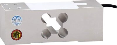
Planar Beam
Planar beam load cells are chosen specifically for their low profile. They frequently appear at the four corners of a scale, trimmed together through a junction box that combines their measurement signals.
Planar beam load cells work well in applications where goods or products are sold commercially by weight. These commercial applications require scales that are “legal-for-trade” or “trade-approved.” Examples include airport luggage scales and grocery scales.
Planar beam load cells typically weigh loads in the 10-400lb range. The lowest capacity in the Tacuna Systems product line is 3.75Kg and the highest is a 375Kg load cell.
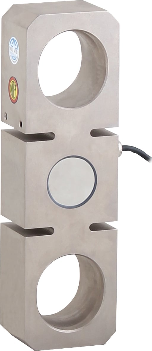
S-Beam Load Cells
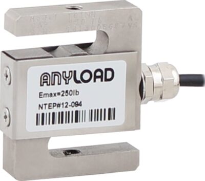
S-beam load cells are powerful because they can be used in both tension and compression. They are durable with high endurance. This makes them ideal for light performance testing such as testing the resistance of doors, hinges, or springs. Their versatility is obvious when you consider the number and diversity of research examples in our “Featured Customer Projects” section of our Knowledge Base that use them. See Cal Poly Rocketry Test Stand Gets off the Ground with Tacuna Systems, Research With Load Cells: Effects of Military Load Carriage on Ground Reaction Forces, Load Cells in Education: Neuromuscular Aspects of Human Movement Force Measurement, and Next-Gen Transmissions for High-Performance Hybrid Cars.
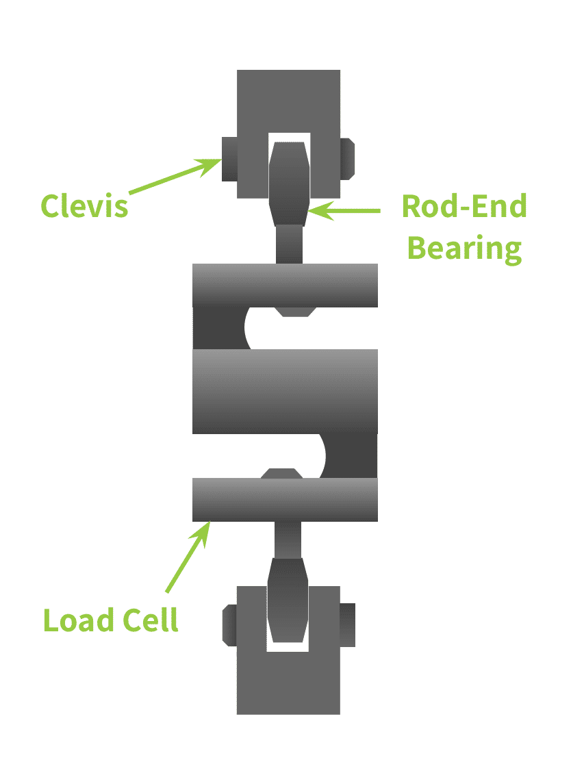
These load cells are, however, susceptible to large bending moments due to their geometry. Rod-end bearings and clevises help orient the load path in the desired direction. Likewise, quality load cells will resist and compensate for this issue.
Tacuna System’s offering of S-type load cells range from a rated capacity of as low as 2Kg to 40,000Kg.
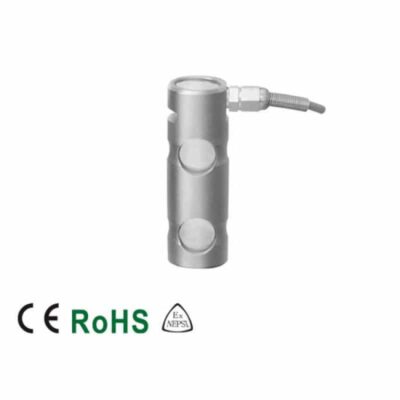
Load Pins
Load pins are designed for suspended systems where a pin supports the structure either in tension or compression. They replace the pin in shackles with clevis pins, sprockets, or pulleys, bearing shear forces from the load. Strain gauges in a bore through the center of the pin measure these forces and deliver real-time measurements. In compression applications, the pin replaces a bolt that supports the load.
Load pins generally have a capacity of up to 100 tons. This makes them ideal for large-load applications.
Tension Link
Tension link load cells are similar to canister load cells but are for suspension applications. Like canister load cells they handle much heavier loads, but are much bulkier than other types. They are designed for crane scales or cable strength tests for loads up to 100 tons.
Tension link load cells typically operate in areas with a wide variety of environmental exposure including construction sites and ports. For this reason they have environmental protections within their design that allow them to withstand heavy amounts of humidity, salt from seawater, and high coastal winds. Their design also makes them resistant to bending loads, side loads, and torsion.
Bending and Shear Force Load Cells
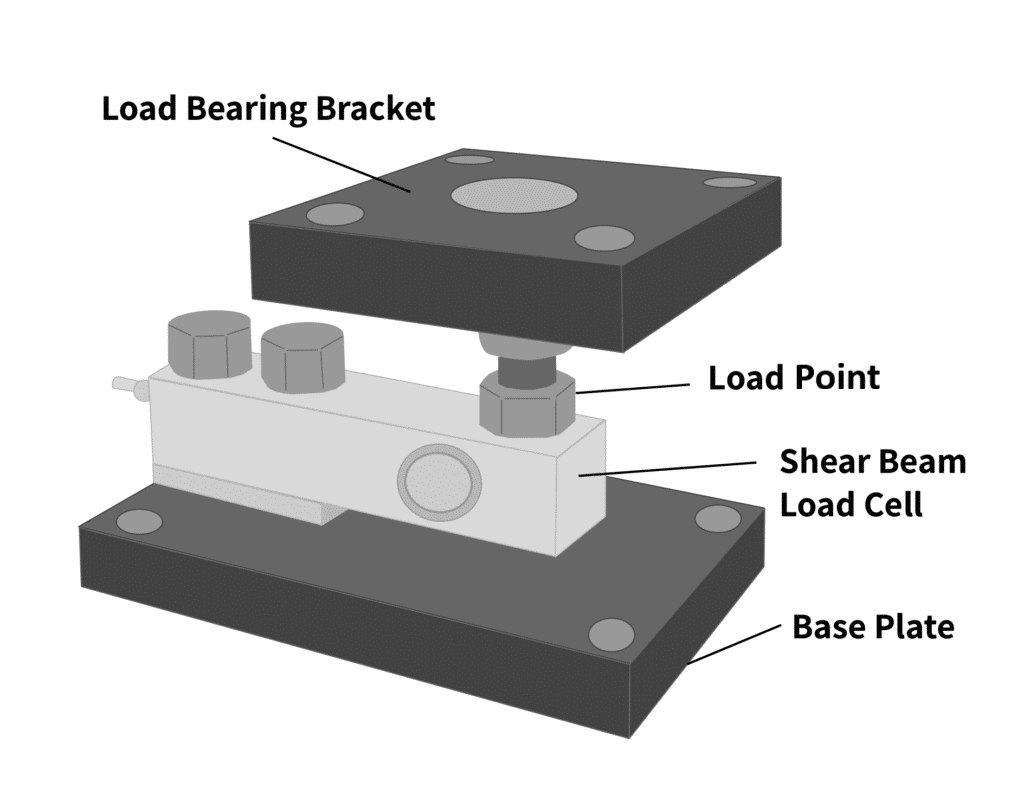
Shear beam load cells are designed to take loads that cause shear stresses or bending moments. The load path through shear beam load cells should align vertically, as these devices do not compensate well for torsion or other significant side loads out of plane with the loading path. Proper mounting can help mitigate misalignment. For more information on load cell mounts, see A Comparison of Tacuna Systems Load Cell Mounts.
Single-Ended Shear Beam
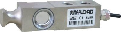
Single-ended shear beams are a simple and affordable load cell option for medium capacities (2 – 2650 lb). One end of the beam is fixed while a load is applied to the free end, as Figure 15 below shows.
The shear beam deforms under an applied force, allowing the strain gauges to equate a load based on the amount of bending it experiences. These load cells are ideal when there is a narrow physical space between the load cell and its mount or fixture. Single-ended shear beam load cells are also practical for large weighing applications where multiple load cells combine to form a single measurement system. Examples of these applications include tanks, hoppers, and other vessels.
Again, our customers have come up with some interesting uses for this type of load cell. See Load Cell Research Example: Hydrodynamic Characteristics of Freshwater Snails for one such example.
Double-Ended Shear Beam
Double-ended shear beam load cells function similarly to single ended. However, double-ended beams are fixed at both ends and the load is applied to the midway point.
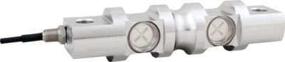
Double-ended shear beams have higher load capacity ratings than single-ended. Therefore, applications with higher weight requirements and narrow size constraints should opt for these. Double-ended shear beams appear in industrial weighing applications such as floor-scales, weighing tanks, and other vessels. Tacuna Systems offers double-ended shear beam load cells rated from 1000-400,000 lbs.
Torque Transducers
These transducers, like other load cell transducers, convert mechanical inputs into a quantifiable electrical signal. Torque cells specifically detect torsional input. In other words, they detect forces that cause the body to twist.
Most torque transducers use full or half Wheatstone bridge strain-gauge configurations. The gauges typically measure the applied loads causing shear strain and bending strain and combine these outputs to quantify torsion or torque.
The two main types of torque transducers are static and rotating.
Static Torque Transducers
Static devices are used when one end of the shaft or measured body is fixed to a non-moving frame. Creating them is simple and easy to accomplish with conventional strain gauges and wiring.
Rotating Torque Transducers
Rotating parts, like driveshafts or propeller masts, are more difficult to measure due to their rotation. Connecting wires to a rotating object creates a need for engineering solutions like slip-rings or wireless transmission.
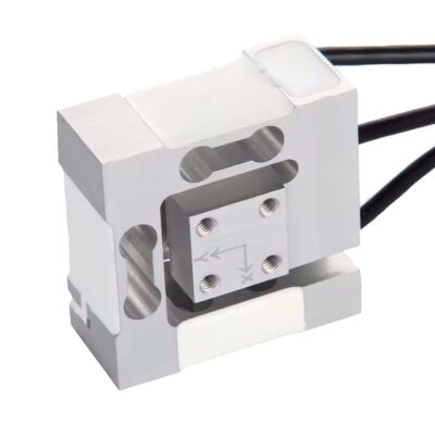
Three-Axis Load Cell
A 3-axis load cell measures forces simultaneously in the X, Y, and Z directions, making it suitable for applications where both the magnitude and direction of forces are important. This device measures each force component independently, allowing for the capture of not only the total force on a body in a particular physical orientation, but each component vector as well.
These sensors are commonly used in robotics, fixturing, and test systems where side loads, shear forces, and compressive loads occur together.
6) Summary
Load cell class ratings and other load cell approval markings can provide a quick understanding of a load cell’s specifications. The following articles explain these approvals further: Load Cell Classes: NIST Requirements, Load Cell Classes: OIML Requirements, and Measurement System Compliance Certificates and Approvals Explained.
The table below summarizes the features of the strain gauge load cell categories sold by Tacuna Systems, and which load cell to choose for a general application. For guidance on which material to choose for a type of load cell, see this FAQ answer. For an overview of load cells that are safer or more practical in applications where wiring an excitation voltage is not recommended, see our article of that same name.
Summary of Load Cell Types and Their Application
| Type | Material | IP Rating | Application |
|---|---|---|---|
| Disk/Canister | Aluminum, Alloy Steel, Stainless Steel | IP66, IP67, IP68 | Heavy compression loads |
| Double-Ended Shear Beam | Aluminum, Alloy Steel, Stainless Steel, Tool Steel | IP66, IP67, IP69 | Floor scales and heavy-duty weighing scales for trucks, vessels and tanks |
| Load Pin | Stainless Steel | IP67 | Industrial, aeronautical and marine environments |
| Miniature | Aluminum, Stainless Steel | IP66, IP67 | Industry computerization, automation, cable testing, pneumatic and hydraulic controls |
| Planar Beam | Aluminum, Alloy Steel | IP65 | Postal scales, retail checkout scales, medical equipment, airport baggage scales |
| Single Point | Aluminum, Alloy Steel, Stainless Steel | IP66, IP67 | Industrial scales, filling and packaging systems, on-board weighing systems, medical equipment |
| Single-Ended Shear Beam | Aluminum, Alloy Steel, Stainless Steel | IP65, IP66, IP67, IP68 | Industrial floor scales, barrel scales, low to medium capacity vessel weighing |
| S-Type, S-Beam | Aluminum, Alloy Steel, Stainless Steel | IP65, IP67, IP68 | Automotive components, polymer strain testing, industrial food processing |
| Tension Link | Alloy Steel, Stainless Steel | IP65, IP67, IP68, IP69K | Cable and towing tension, crane and hoist scales, tensile verification systems |
References
- Mechanics of Materials, 9th edition, Russell C. Hibbeler
- Measurement and Instrumentation in Engineering: Principles and Basic Laboratory Experiments, 1st Edition, Francis S. Tse, Ivan E. Morse
- ISO 7500-1, Metalic Materials – Verification of Static Uniaxial Testing Machines – Part 1: Tension/Compression Testing Machines – Verification and Calibration of Force-Measuring System, 3rd Ed, 2004-08-15
- OIML R 60-1, Metrological regulation for load cells Part 1: Metrological and technical requirements, Organisation Internationale de Métrologie Légale, Edition 2017
- NIST Handbook 44, Specifications, Tolerances, and Other Technical Requirements for Weighing and Measuring Devices, as adopted by the 104th National Conference on Weights and Measures, 2019, National Institute of Standards and Technology, US Department of Commerce